
Method for controlling a hydraulic system of a mobile working machine

a mobile working machine and hydraulic system technology, applied in the direction of fluid couplings, positive displacement liquid engines, couplings, etc., can solve the problems of complex load distribution and change, control system cannot allow for one load-dependent reduction in the speed of the internal combustion engine, and cannot be controlled satisfactorily by the method described

Active Publication Date: 2006-08-17
CNH BAUMASCHEN
View PDF8 Cites 21 Cited by
  • Summary
  • Abstract
  • Description
  • Claims
  • Application Information

AI Technical Summary

Problems solved by technology

The control system can only allow for one load-dependent reduction in the speed of the internal combustion engine which has already taken place.
In addition, the method described only allows for the pump for the hydraulic drive of the self-propelled machine.
Complicated load distributions and changes in them during operation, as commonly occur in complex hydraulic systems with multiple pumps and transmission systems, cannot be controlled satisfactorily by the method described.
However, it is necessary for the speed of the diesel engine to have fallen already so that the mechanical overload can be detected.
In addition, if several adjustable pumps are present, their volume displacement will always be reduced uniformly, rendering flexible adjustment to different operating modes of the plant impossible.
The necessity for a so-called inching pedal constitutes a further disadvantage in modern machines.
However, this complicates the operating procedure for the machine, as the operator has to ensure a diesel engine speed high enough to supply the respective hydraulic systems manually, by operating the inching and accelerator pedals, as well as operating the controls for the working functions.

Method used


Image

  • Method for controlling a hydraulic system of a mobile working machine
  • Method for controlling a hydraulic system of a mobile working machine
  • Method for controlling a hydraulic system of a mobile working machine

Examples


Embodiment Construction

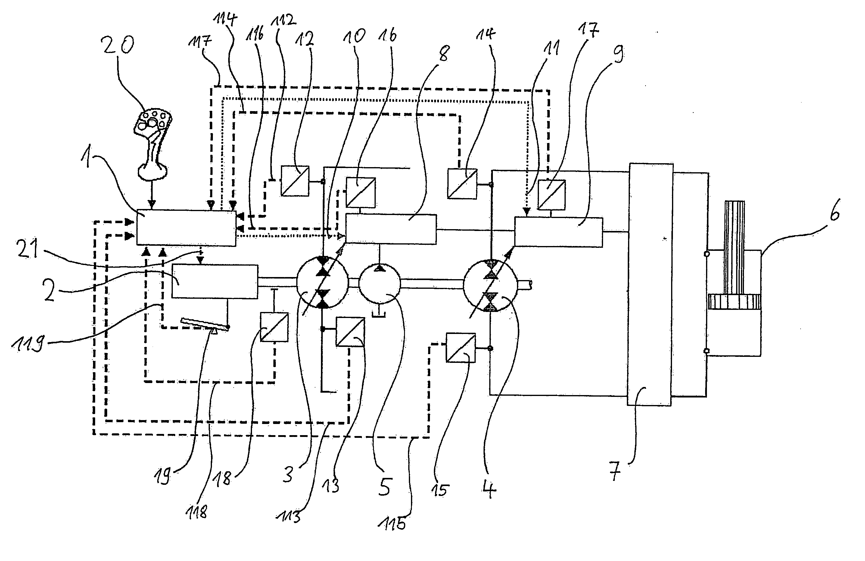
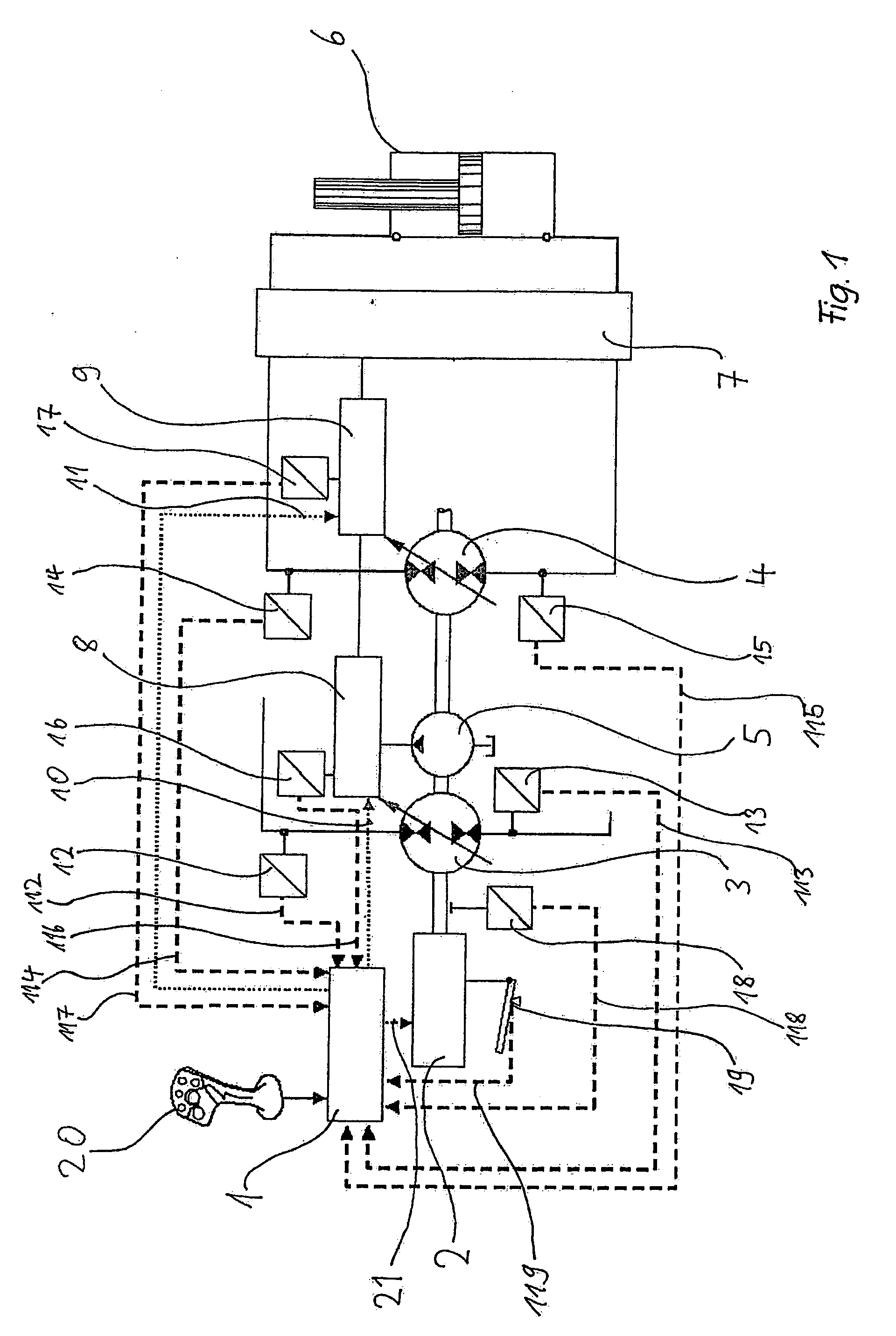
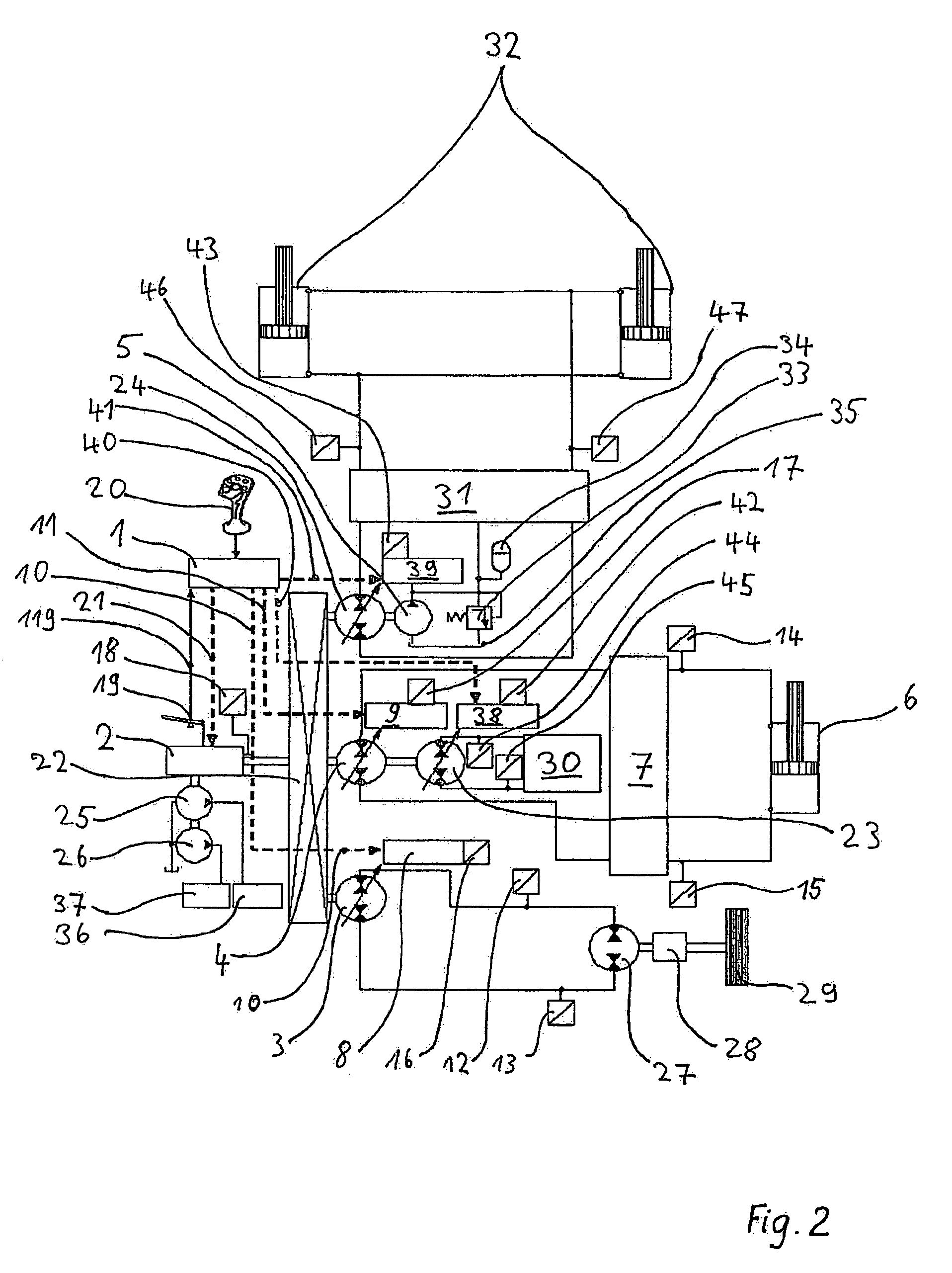
[0029] Referring to FIG. 1, the electronic control system designated 1 is used to control a hydraulic system of a self-propelled working machine. This hydraulic system has an internal combustion engine 2, which drives two pumps with adjustable volumetric displacement 3 and 4 and a fixed-displacement pump 5 in an initial configuration. The adjustable pump 3 is used to drive a hydraulic transmission system with a rotary engine (not shown in more detail here). The adjustable pump 4 drives a displacement-controlled machine hydraulic system with a differential cylinder 6 as a linear motor. A valve manifold 7 (not shown in more detail) ensures the necessary compensation for the difference in volumetric flow and the other necessary hydraulic functions such as overload protection, etc. The fixed-displacement pump 5 and an accumulator charging circuit (not shown in more detail) form the low-pressure system of the machine and supply low pressure to the hydraulically-operated volumetric displa...


PUM


Abstract

A method is described for controlling a hydraulic system, particularly of mobile working machine, with at least one internal combustion engine driving at least one hydraulic pump with adjustable volumetric displacement and possibly additional fixed-displacement pumps

Description

FIELD OF THE INVENTION [0001] The present invention concerns a method for controlling a hydraulic system, particularly of a mobile working machine, with at least one internal combustion engine driving at least one hydraulic pump with adjustable volumetric displacement and possibly additional fixed-displacement pumps. BACKGROUND OF THE INVENTION [0002] A method for controlling the load limit of a hydrostatic drive and a hydrostatic drive for a machine are described in EP 0 497 293 A1. It detects the position of the accelerator and the actual speed of the internal combustion engine present in the machine by means of metrological instruments and feeds these measured values to an electronic control system. A standard deviation is determined from the difference between the actual and target power levels defined by the measured values and a control valve actuated so that the hydraulic pump accepts hydraulic power lower than or equal to the available power of the internal combustion engine...

Claims


Application Information

Patent Timeline
IPC IPC(8): F04B49/06E02F9/22
CPCE02F9/2235E02F9/2246F04B49/065
Inventor IVANTYSYNOVA, MONIKARAHMFELD, ROBERTWEBER, JURGEN
Owner CNH BAUMASCHEN
Learn More