Method for feeding a treating agent to an application apparatus

Inactive Publication Date: 2006-08-17
VALMET TECHNOLOGIES INC
View PDF9 Cites 0 Cited by
  • Summary
  • Abstract
  • Description
  • Claims
  • Application Information

AI Technical Summary

Benefits of technology

[0010] The invention is based on controlling the feeding of a treating agent to an application apparatus on the basis of a treating agent flow measured from a feed line and of the desired set value of the feed. The desired value has been selected so as to provide the desired treating agent amount to a web or to a transfer surface. This kind of flow control makes

Problems solved by technology

Return circulation causes many practical problems.
Supplying too much treating agent increases leakages.
If too small amounts of treating agent are supplied, there is a risk of an uneven application profile.
It is difficult to use pressure control for adjusting the amount of coating.
A further disadvantage is that the increase of loading pressure wears effectively both the groovin

Method used


Image

  • Method for feeding a treating agent to an application apparatus
  • Method for feeding a treating agent to an application apparatus
  • Method for feeding a treating agent to an application apparatus

Examples


Example

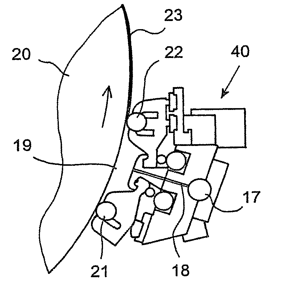
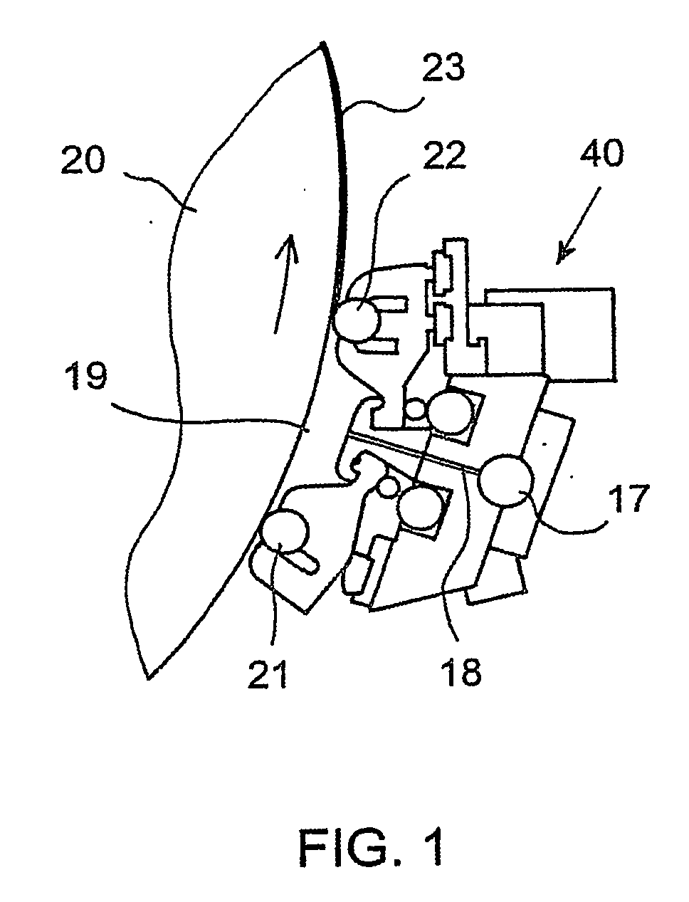
[0018]FIG. 1 shows a cross-sectional view of a treating agent application apparatus 40 associated with a film transfer coater. It comprises an application chamber 19 arranged against a curved surface of an applicator roll 20. The treating agent is supplied to the application apparatus 40 via a distributor pipe 17, wherefrom it passes to the application chamber 19 via nozzle ducts 18. Part of the feed flow passed to the distributor pipe is discharged as a bypass flow through the opposite end of the pipe. The application chamber 19 is confined on the ingoing side, when seen in the direction of movement of the roll 20, by a sealing rod 21 and on the exit side by an applicator rod 22, each of which is arranged to rotate in its cradle, via which said rod 21, 22 is loaded against the surface of the roll 20. The loading of the sealing rod 21 and the applicator rod 22 is controlled such that the treating agent is only able to discharge from the application chamber 19 through grooves in the ...


PUM

PropertyMeasurementUnit
Flow rateaaaaaaaaaa
Coloraaaaaaaaaa
Sizeaaaaaaaaaa

Abstract

A treating agent is fed to an application apparatus (40) used for applying coating color or surface size directly or indirectly to a paper or board web. Part of the treating agent fed to the application apparatus (40) is returned via a bypass line (24) to the treating agent feed system and part of it is passed into an application chamber in the application apparatus (40), from which application chamber substantially all treating agent fed into it is applied to a moving web or to a transfer surface. The flow of a treating agent (Q) to the application apparatus (40) is measured, and the feeding of the treating agent is controlled on the basis of the measured flow (Q) and of a predetermined set value (Q0), which set value has been selected according to the desired amount of treating agent to be applied to the moving web or transfer surface.

Description

CROSS REFERENCES TO RELATED APPLICATIONS [0001] This application is a U.S. national stage application of International App. No. PCT / FI2004 / 000120, filed Mar. 4, 2004, the disclosure of which is incorporated by reference herein, and claims priority on Finnish App. No. 20030340, Filed Mar. 6, 2003. STATEMENT AS TO RIGHTS TO INVENTIONS MADE UNDER FEDERALLY SPONSORED RESEARCH AND DEVELOPMENT [0002] Not applicable. BACKGROUND OF THE INVENTION [0003] The invention relates to a method for feeding a treating agent to an application apparatus used for applying coating color or surface size directly or indirectly to a paper or board web. In the method, part of the treating agent fed to the application apparatus is returned via a bypass line to the treating agent feed system and part of it is passed into an application chamber in the application apparatus, from which application chamber substantially all treating agent fed into it is applied to a moving web or to a transfer surface. [0004] The...

Claims


Application Information

Patent Timeline
IPC IPC(8): B05D3/12B05C3/18B05C11/10D21H23/48D21H23/56D21H23/78G05D7/06
CPCB05C3/18B05C11/10B05C11/1039D21H23/48D21H23/56D21H23/78G05D7/0676B05C11/1013
Inventor VATANEN, HEIKKIPITKANIEMI, TAPIOPAIVA, PETRILAUKKANEN, TAPIOLUOSARINEN, IIRONURMIAINEN, TIMOVIITANEN, MARKKU
Owner VALMET TECHNOLOGIES INC
Why Eureka
Try Eureka