Method for analyzing electrolytic copper plating solution, and analyzing device therefor and production method for semi-conductor product

a technology of electrolytic copper and plating solution, which is applied in the direction of semiconductor/solid-state device testing/measurement, instruments, and material electrochemical variables, can solve the problems of worsening fillability of plating solution, and achieve the effect of satisfying fillability

Inactive Publication Date: 2006-08-17
TOPPAN PRINTING CO LTD
View PDF11 Cites 13 Cited by
  • Summary
  • Abstract
  • Description
  • Claims
  • Application Information

AI Technical Summary

Benefits of technology

[0026] The invention of claim 21 is a method for fabricating a semiconductor product, which comprises using the method for analyzing a copper electroplating solution of claim 19 and controlling the condition of the solution

Problems solved by technology

In spite of the assertion, that CV is usable as an additive control apparatus and of the effectiveness of commercially-available CVS apparatus, there are posed many technical problems.
For example, in copper electroplating for filling via

Method used


Image

  • Method for analyzing electrolytic copper plating solution, and analyzing device therefor and production method for semi-conductor product
  • Method for analyzing electrolytic copper plating solution, and analyzing device therefor and production method for semi-conductor product
  • Method for analyzing electrolytic copper plating solution, and analyzing device therefor and production method for semi-conductor product

Examples


example 1

[0086] The invention of claims 1 to 6 is described in detail with reference to the following Examples 1 to 3. The apparatus used has the constitution as in FIG. 6. 100 ml of a plating solution of which the additive concentration was controlled through CVS. analysis (plating solution sample 5) was sampled from a via-filling copper plating bath actually in service, and this was put into a beaker and set on a stand 6 for its exclusive use. However, since the plating solution sample changes while left, it was used for the test within 2 days after its sampling.

[0087] As the reference electrode 2, used was a two-layer-structured Ag / AgCl reference electrode (the external solution is 10 vol. % H2SO4; the internal solution is 0. lmol / liter KCl; and Ag / AgCl is in the internal solution, 10 vol. % H2SO4); as the working electrode 3, used was a platinum rotary electrode (electrode area 4 πmm2); and as the counter electrode 4, used was a copper column (diameter 8 mm).

[0088] The electric current...

example 2

[0090] From a via-filling copper plating bath actually in service, the plating solution was sampled at intervals of 2 months, and subjected to constant-current potential measurement under the same condition as in Example 1. The additive concentration of the solution was controlled to be constant through CVS analysis.

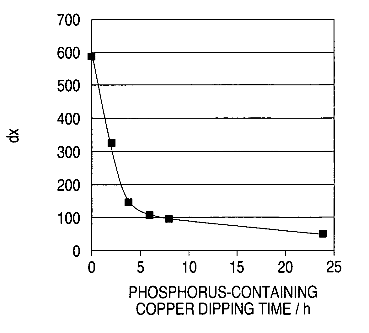
[0091]FIG. 13 shows the result of measurement of the constant-current potential of a fresh solution having the same additive concentration as that of the above solution, and that of the plating solution sampled at intervals of 2 months. FIG. 14 shows dx of the result of measurement of the constant-current potential inFIG. 13. From FIGS. 13 and 14, it is understood that, even though the additive concentration was controlled to be constant through CVS analysis, the fillability still lowered.

example 3

[0092] A fresh solution was prepared and divided into two. Nothing was put into one; and a phosphorus-containing copper plate with a controlled area of 100 cm2 / liter was put into the other and statically left as it was for 48 hours. Using the two solutions, a via-hole having a diameter of 100 μm and a depth of 75 μm was plated. With the former solution, the via-hole was filled, but not with the latter.

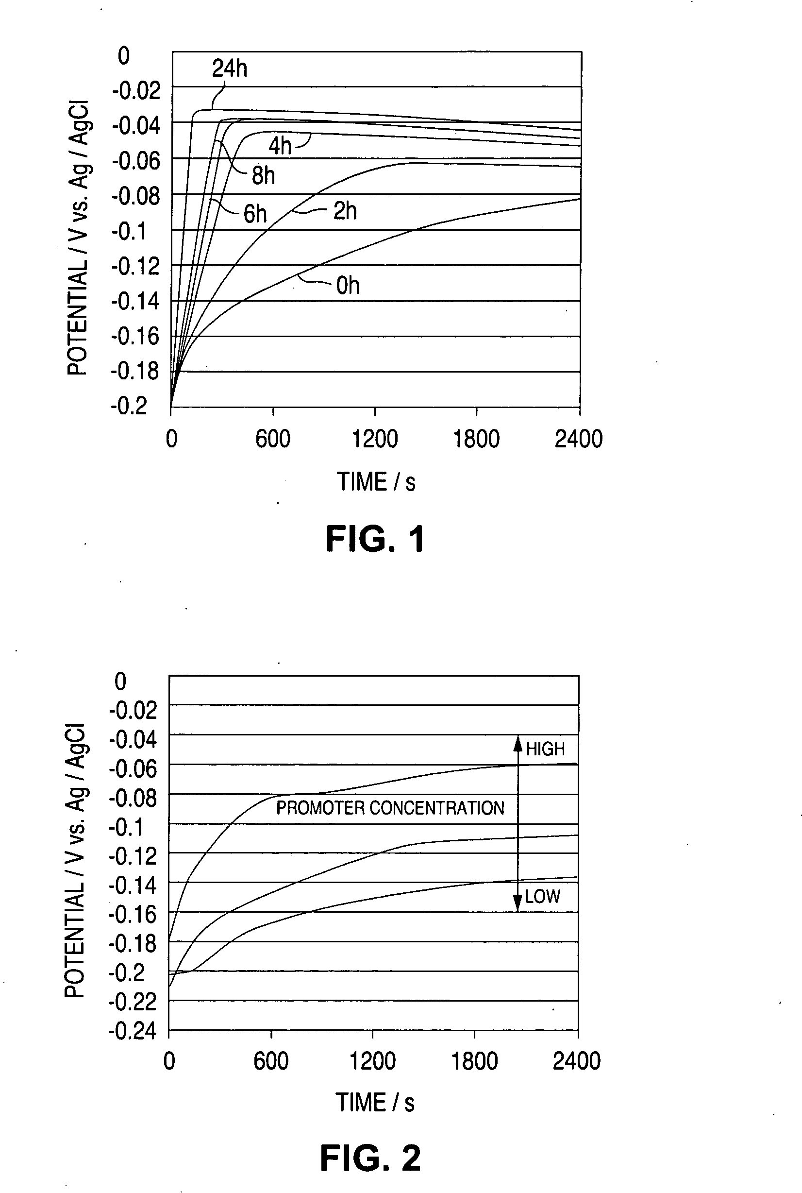
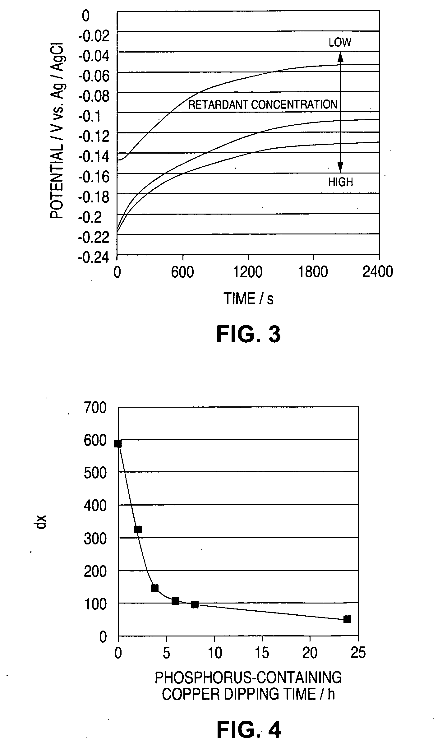
[0093] Both solutions were subjected to CVS analysis to determine the promoter concentration and the retardant concentration therein, but the difference between the two was only on a level of error. From this, it may be said that the additive concentration control through CVS analysis is not enough to judge the via fillability.


PUM


Abstract

Effective fillability and the uniformity electrodeposition of a copper electroplating solution is judged by determining the time-dependent potential change thereof at a cathode current density of 0.1-20 A/dm2. The potential change is determined at a working electrode rotation of 100-7500 rpm, and the fillability with the solution is judged from the curve profile. The time-dependent potential change curve within a predetermined period of time after the start of electrolysis is approximated according to the Boltzmann's function, and the potential change speed dx and the potential convergent point A2 are obtained to judge the fillability with a plating solution.

Description

TECHNICAL FIELD [0001] The present invention relates to a method for analyzing a copper electroplating solution used in copper electroplating for filling a copper metal in a via-hole or a trench installed in printed circuit boards, semiconductor package substrates or semiconductor products such as semiconductor substrates, and to an apparatus for the analysis and to a method for producing a semiconductor product. The present application is based on Japanese Patent Application No.2003-082037 and Japanese Patent Application No. 2003-350544, of which the disclosures are hereby incorporated. BACKGROUND ART [0002] In general, additives are used in a copper electroplating solution. Additives include a promoter and a retardant, and when added to a plating solution, then the plating on the bottom of a via-hole is promoted while that outside the via-hole is retarded whereby the via-hole is filled with a plating metal. To attain the phenomenon, the promoter and the retardant used must be well...

Claims


Application Information

Patent Timeline
IPC IPC(8): H01L21/66H01L21/44C25D21/12G01N27/416G01N27/42
CPCC25D21/12G01N27/42G01N27/416
Inventor OKUBO, TOSHIKAZUNAOI, KATSUYOSHIYAMADA, YUKA
Owner TOPPAN PRINTING CO LTD
Why Eureka
Try Eureka