Steerable catheter with in-plane deflection

a steerable catheter and in-plane technology, applied in the field of improved steerable catheters, can solve the problems of difficult limitation of out-of-plane deflection and catheter tip deflection, and achieve the effect of less greater effective or combined area momen

Active Publication Date: 2006-08-17
BIOSENSE WEBSTER INC
View PDF54 Cites 102 Cited by
  • Summary
  • Abstract
  • Description
  • Claims
  • Application Information

AI Technical Summary

Benefits of technology

[0009] In one embodiment, the deflection mechanism comprises one deflection member having a generally rectangular cross section with a width W along an x axis and a thinness T along a y axis, wherein the area moment of inertia along the x axis Ix and the area moment of inertia along the y axis Iy are defined as follows: Ix=(W)⁢ ⁢T312Iy=(T)⁢ ⁢W312
[0010] In an alternative embodiment, the deflection mechanism comprises a plurality of deflection members, each of which contributes to an effective or combined area moment of inertia along an x axis and an effective or combined area moment of inertia along a y axis, which biases the tip section to deflect in a plane parallel with the centroidal axis with the greater effective area moment of inertia and resist deflection in a plane parallel with the centroidal axis with the lesser effective area moment of inertia.
[0011] In a detailed embodiment, a catheter with in-plane deflection comprises a catheter body having proximal and distal ends and a lumen extending therethrough and a tip section at the distal end of the catheter body. The tip section comprises a flexible plastic tubing having a pair of diametrically-opposed lumens extending therethrough. The catheter also provides two puller wires manipulated through a control handle at the proximal end of the catheter body. The deflection mechanism is configured with a lesser area moment of inertia about a first centroidal axis and a greater area moment of inertia about a second centroidal axis generally orthogonal to the first centroidal axis so as to bias deflection of the tip section in a plane parallel with the second centroidal axis with the greater area moment of inertia and resist deflection in a plane parallel with the first centroidal axis with the lesser area moment of inertia.
[0012] In a more detailed embodiment, a catheter with in-plane deflection has a deflection mechanism comprising a single elongated deflection member positioned between the puller wires, the deflection member having a cross-section with a thicker dimension and a thinner dimension so as to bias a tip section to deflect in a plane parallel with the thinner dimension and resist deflection in a plane parallel with the thicker dimension.
[0013] In another more detailed embodiment, a catheter with in-plane deflection has a deflection mechanism comprising a plurality of elongated deflection members that are configured to provide a lesser effective or combined area moment of inertia about a first centroidal axis and a greater effective or combined area moment of inertia along a second centroidal axis. The deflection members jointly bias the tip section of the catheter to deflect in a plane parallel with the second centroidal axis and to resist deflection in a plane parallel with the first centroidal axis

Problems solved by technology

In this arrangement, lengthwise movement of the piston relative to the housing results in deflection of the catheter tip section.
However, because the tip section is generally made of a flexible material, it is sometimes difficult to limit out-of-plane deflection.

Method used


Image

  • Steerable catheter with in-plane deflection
  • Steerable catheter with in-plane deflection
  • Steerable catheter with in-plane deflection

Examples


Embodiment Construction

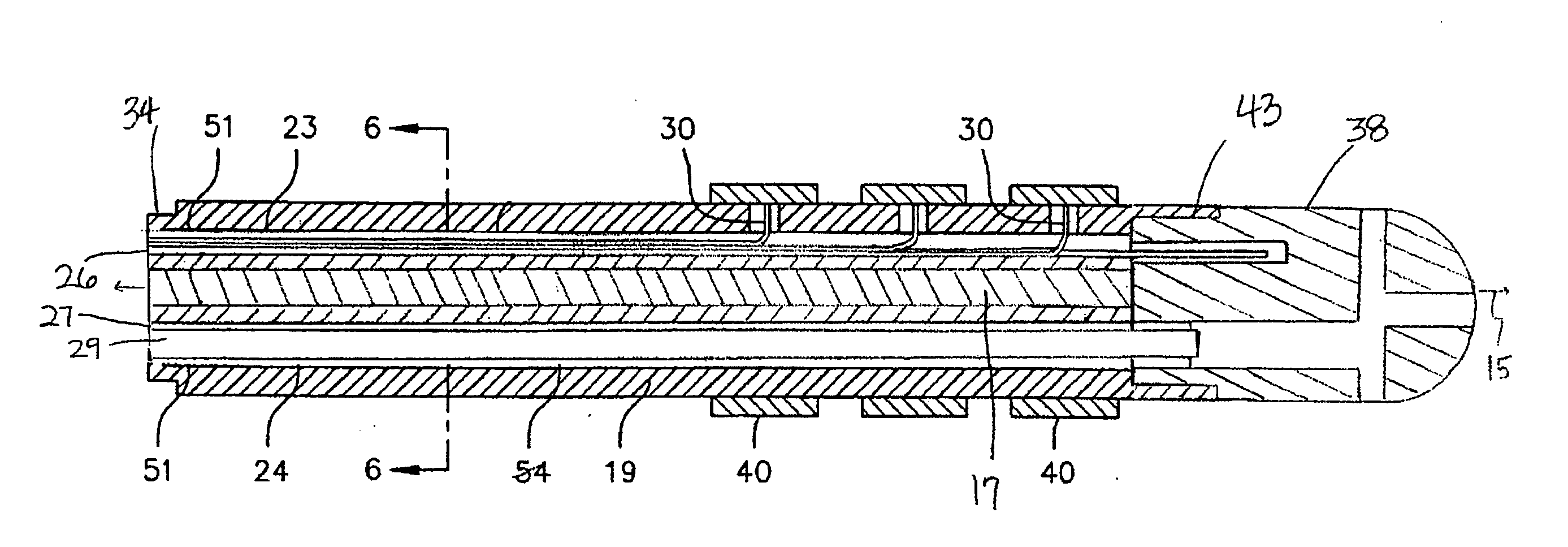
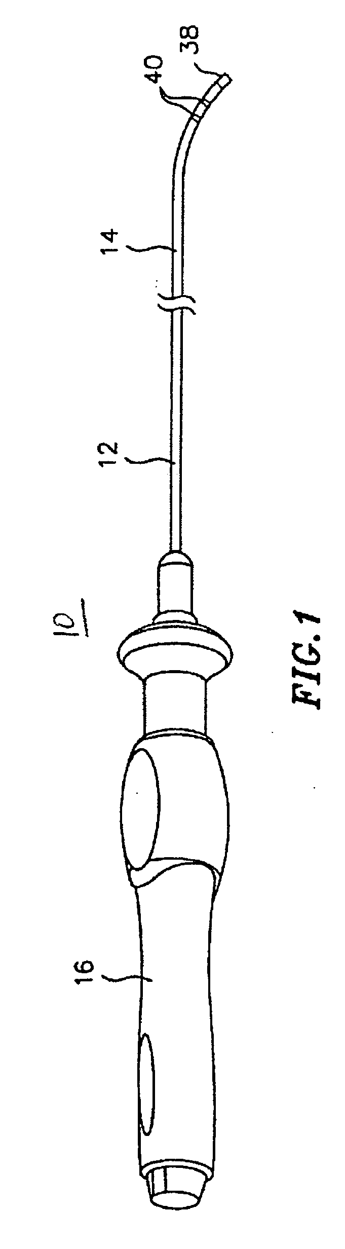
[0033] In an embodiment of the invention, there is provided a steerable bidirectional electrode catheter. As shown in FIG. 1, the catheter 10 comprises an elongated catheter body 12 having proximal and distal ends, a tip section 14 at the distal end of the catheter body 12, and a control handle 16 at the proximal end of the catheter body 12.

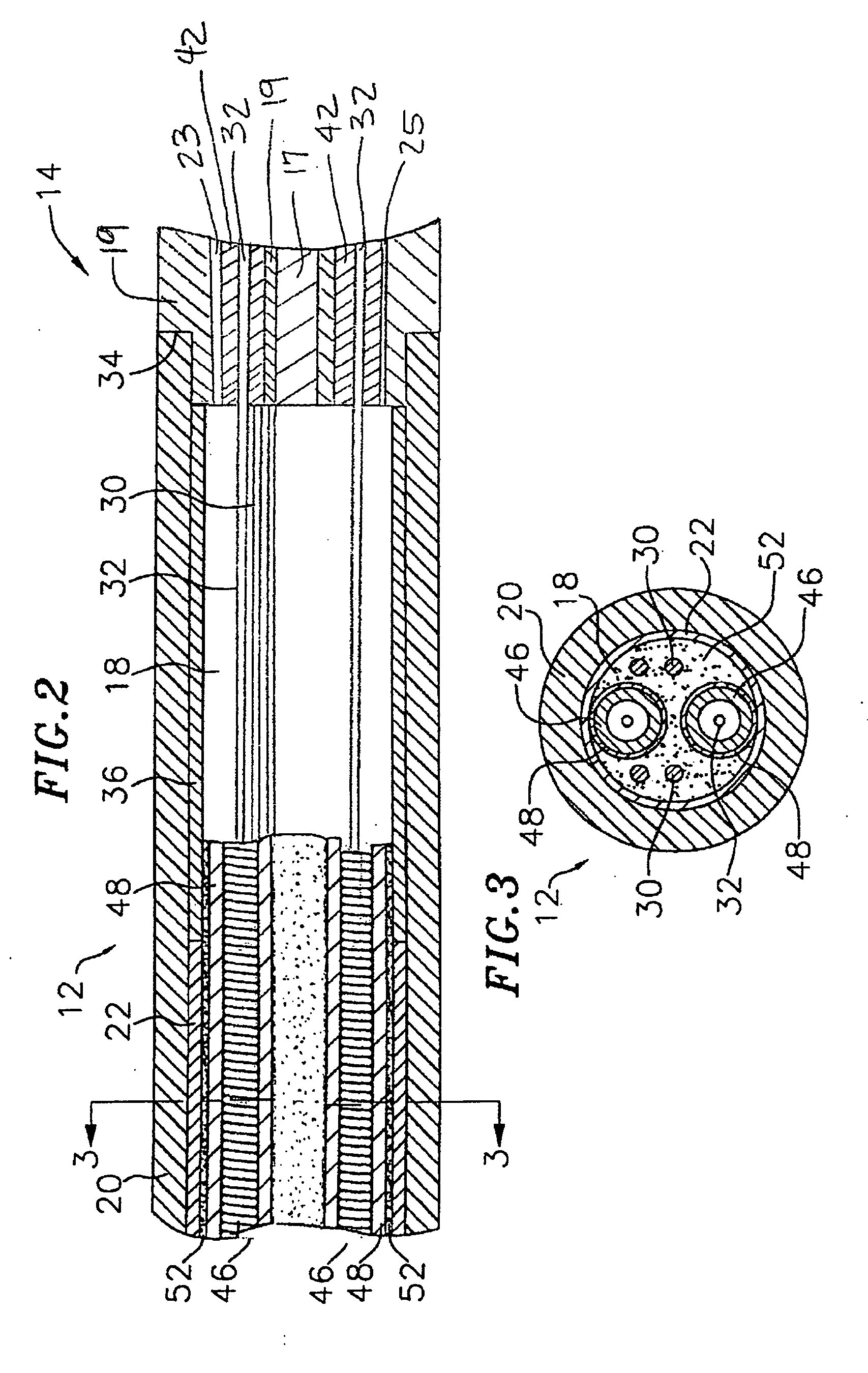
[0034] As shown in FIGS. 2 and 3, the catheter body 12 comprises an elongated tubular construction having a single axial or central lumen 18. The catheter body 12 is flexible, i.e., bendable, but substantially non-compressible along its length. The catheter body 12 can be of any suitable construction and made of any suitable material. A presently preferred construction comprises an outer wall 20 made of polyurethane or PEBAX. The outer wall 20 preferably comprises an imbedded braided mesh of stainless steel or the like to increase torsional stiffness of the catheter body 12 so that when the control handle 16 is rotated the tip section 14 will ro...


PUM


Abstract

An improved steerable catheter with in-plane deflection comprises a catheter body having proximal and distal ends and a lumen extending therethrough and a tip section at the distal end of the catheter body. The tip section comprises a flexible plastic tubing having a pair of diametrically-opposed lumens extending therethrough. The catheter also provides two puller wires manipulated through a control handle at the proximal end of the catheter body. Each puller wire extends through one of the pair of lumens in the tip section and through the lumen of the catheter body and is anchored to the control handle at its proximal end and anchored to the tip section at its distal end. The deflection mechanism is configured to generally define a plane along which deflection most readily occurs and an edge along which deflection is most readily avoided. The deflection mechanism extends longitudinally along a centerline of the tip section between the first and second puller wire and is configured generally with a cross section having a thinner dimension and a thicker dimension to bias the tip section to deflect in a plane parallel with the thinner dimension of the deflection mechanism and to resist deflection in a plane perpendicular to thicker dimension.

Description

FIELD OF INVENTION [0001] The present invention relates to an improved steerable catheter, in particular, a bi-directional catheter with in-plane deflection. BACKGROUND OF INVENTION [0002] Electrode catheters have been in common use in medical practice for many years. They are used to stimulate and map electrical activity in the heart and to ablate sites of aberrant electrical activity. [0003] In use, the electrode catheter is inserted into a major vein or artery, e.g., femoral artery, and then guided into the chamber of the heart which is of concern. Within the heart, the ability to control the exact position and orientation of the catheter tip is critical and largely determines how useful the catheter is. [0004] Steerable (or deflectable) catheters are generally well-known. For example, U.S. Pat. No. RE 34,502 describes a catheter having a control handle comprising a housing having a piston chamber at its distal end. A piston is mounted in the piston chamber and is afforded length...

Claims


Application Information

Patent Timeline
Patent Type & Authority Applications(United States)
IPC IPC(8): A61M31/00
CPCA61B18/1492A61M25/0147A61M25/0144A61B2017/003
Inventor MCDANIEL, BENJAMIN D.SELKEE, THOMAS V.
Owner BIOSENSE WEBSTER INC
Why Eureka
Try Eureka