Foundations for constructions

Inactive Publication Date: 2006-08-24
REPOWER SYST AG
View PDF8 Cites 35 Cited by
  • Summary
  • Abstract
  • Description
  • Claims
  • Application Information

AI Technical Summary

Benefits of technology

[0041] The method according to the invention is particularly practical for use in offshore constructions, since the logistical requirements there, particularly also with regard to the necessary machines for introducing the piles into the ground, can be met economically.
[0042] The invention

Problems solved by technology

The tower and the foundation in particular are components in respect of which the size of the component increasingly poses a problem.
Thus, for example the road transport of the towers, which are made predominantly of steel tubes, poses problems if the diameter of the tower is to be more than 4.3 meters.
In general the headroom of bridges is no longer sufficient to enable a transport laden with the tower or a section of the tower to pass under a bridge.
Furthermore, the available rolling mills and welding processes limit the wall thickness and also the diameter of the machinable cylindrically rolled steel sheets.
In addition the permissible transport weight of currently approximately 100 tons unit weight also limits the dimensions, so that higher unit weights also lead to substantially higher costs.
The foundation of an installation constitutes a considerable cost factor, particularly with regard to the offshore arrangement of wind power installations, i.e. wind power installations erected in the sea.
Apart from the installation and maintenance costs which in any case are already much higher, this cost factor exerts a very strong cost pressure on the offshore use of wind power, and therefore particularly in the case of the cost-intensive foundation attempts are being made to find the

Method used


Image

  • Foundations for constructions
  • Foundations for constructions
  • Foundations for constructions

Examples


Embodiment Construction

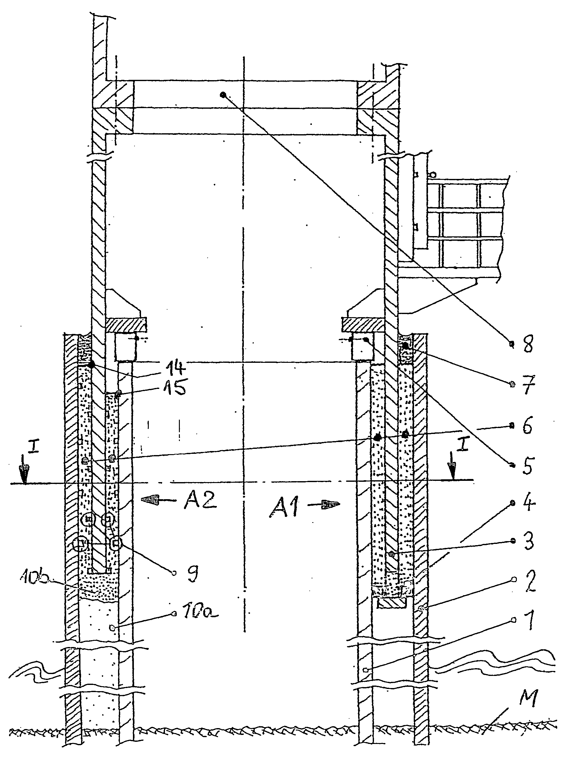
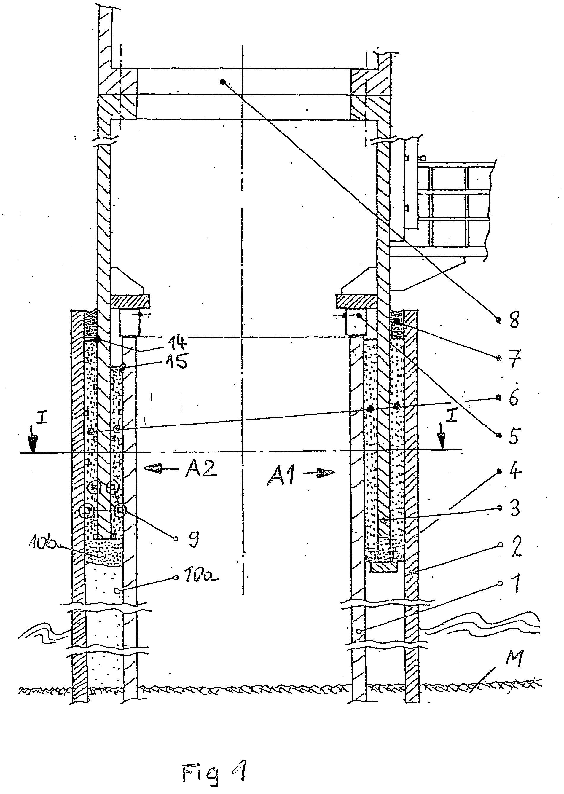
[0052] Two different embodiments A1 and A2 of the invention, which in reality are usually of rotationally symmetrical design, are shown to the left and to the right of the vertical dash-dot line of symmetry. However, in the case of wind power installations which are exposed to high winds or high waves, for economic reasons, it may also be sensible to use different filling material over the circumference of the pile according to the prevailing direction of the high winds or high waves (e.g. inexpensive gravel in the secondary loading direction and high-grade filling material, e.g. grout, in the main loading direction).

[0053] An inner tube 1 and an outer tube 2 are introduced into the seabed (M). The junction piece 3, which is provided at the upper end with a conventional screw flange as connection to the rest of the construction 8, is pushed into the gap between the inner tube 1 and the outer tube 2.

[0054] In the embodiment A1, on the right-hand side only, the region of the concret...


PUM


Abstract

A construction including at least one pile-type device that is anchored in or on the ground and essentially consists of a longitudinal pile element. The pile-type device also includes at least one reinforcement element, which is configured and located in such a way that a gap is formed between the reinforcement element and the pile element. The gap can be filled at least partially with at least one loose and/or free-flowing material.

Description

BACKGROUND OF THE INVENTION [0001] The present invention relates to a foundation for constructions, such as for example wind power installations. [0002] Due to terrific technical development in recent years wind power installations have reached dimensions and weights which are increasingly at the limits of what is technologically feasible. The rotor of such a wind power installation has a diameter which is significantly more than 100 meters, the height of the tower can be up to 130 meters and the mass of a machine housing disposed on the tower can be up to 500 tons. The above-mentioned dimensions and weights nowadays belong to the prior art. [0003] The tower and the foundation in particular are components in respect of which the size of the component increasingly poses a problem. Thus, for example the road transport of the towers, which are made predominantly of steel tubes, poses problems if the diameter of the tower is to be more than 4.3 meters. In general the headroom of bridges...

Claims


Application Information

Patent Timeline
IPC IPC(8): E02D27/00E02D27/12E02D27/42
CPCE02B2017/0091E02D27/12E02D27/42F03D11/04F03D11/045F05B2240/95Y02E10/727F03D13/22F03D13/25Y02E10/72E02D27/44
Inventor EUSTERBARKEY, CARSTEN
Owner REPOWER SYST AG
Why Eureka
Try Eureka