
Method for casting composite ingot

a composite metal and ingot technology, applied in the direction of thin material handling, transportation and packaging, etc., can solve the problems of difficult roll difficulty in controlling the method, and difficulty in rolling-bonding of aa5000 series alloys to other alloys, so as to facilitate metallurgical bonding and better control

Inactive Publication Date: 2006-08-24
NOVELIS INC
View PDF17 Cites 36 Cited by
  • Summary
  • Abstract
  • Description
  • Claims
  • Application Information

AI Technical Summary

Benefits of technology

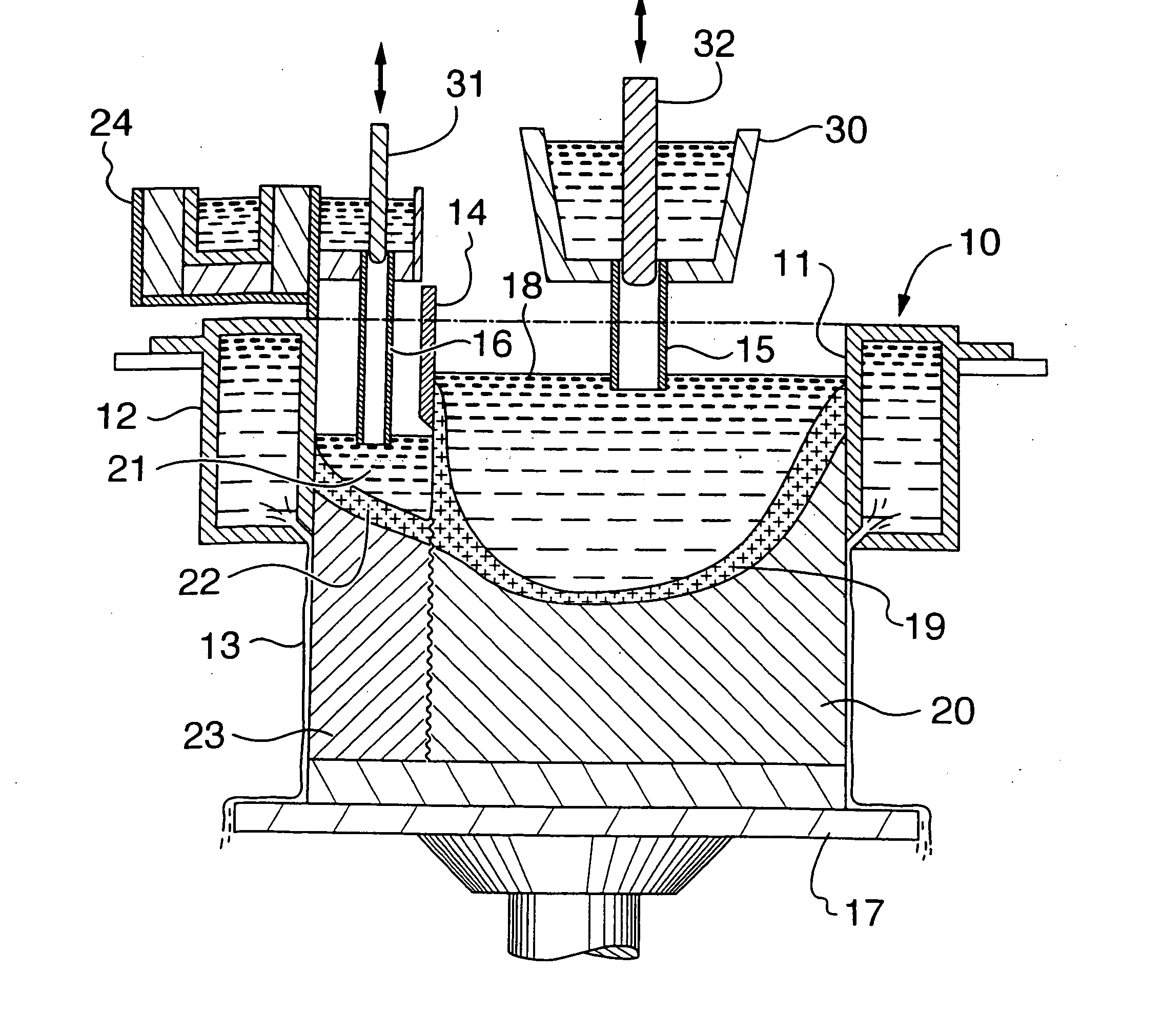
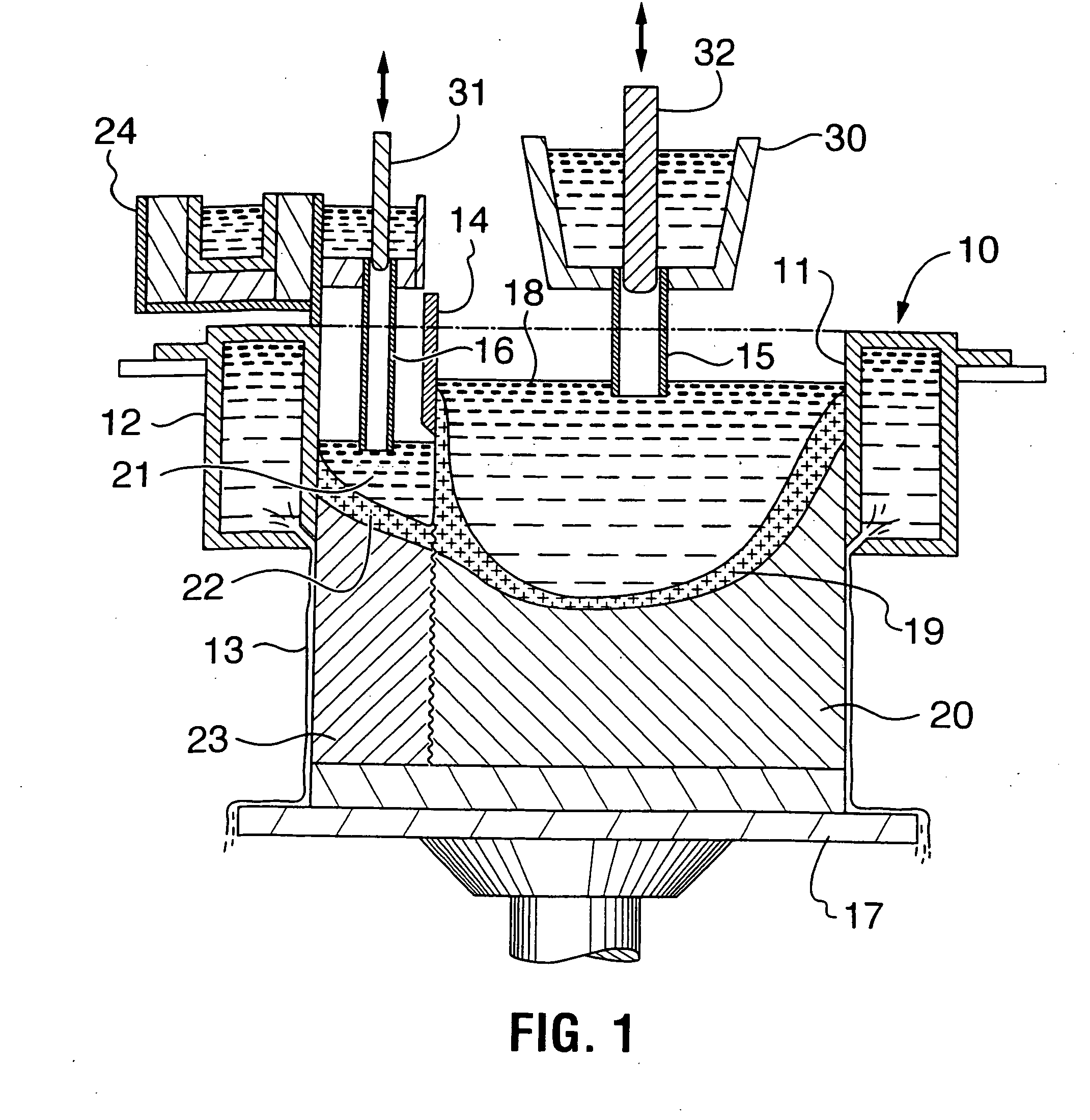
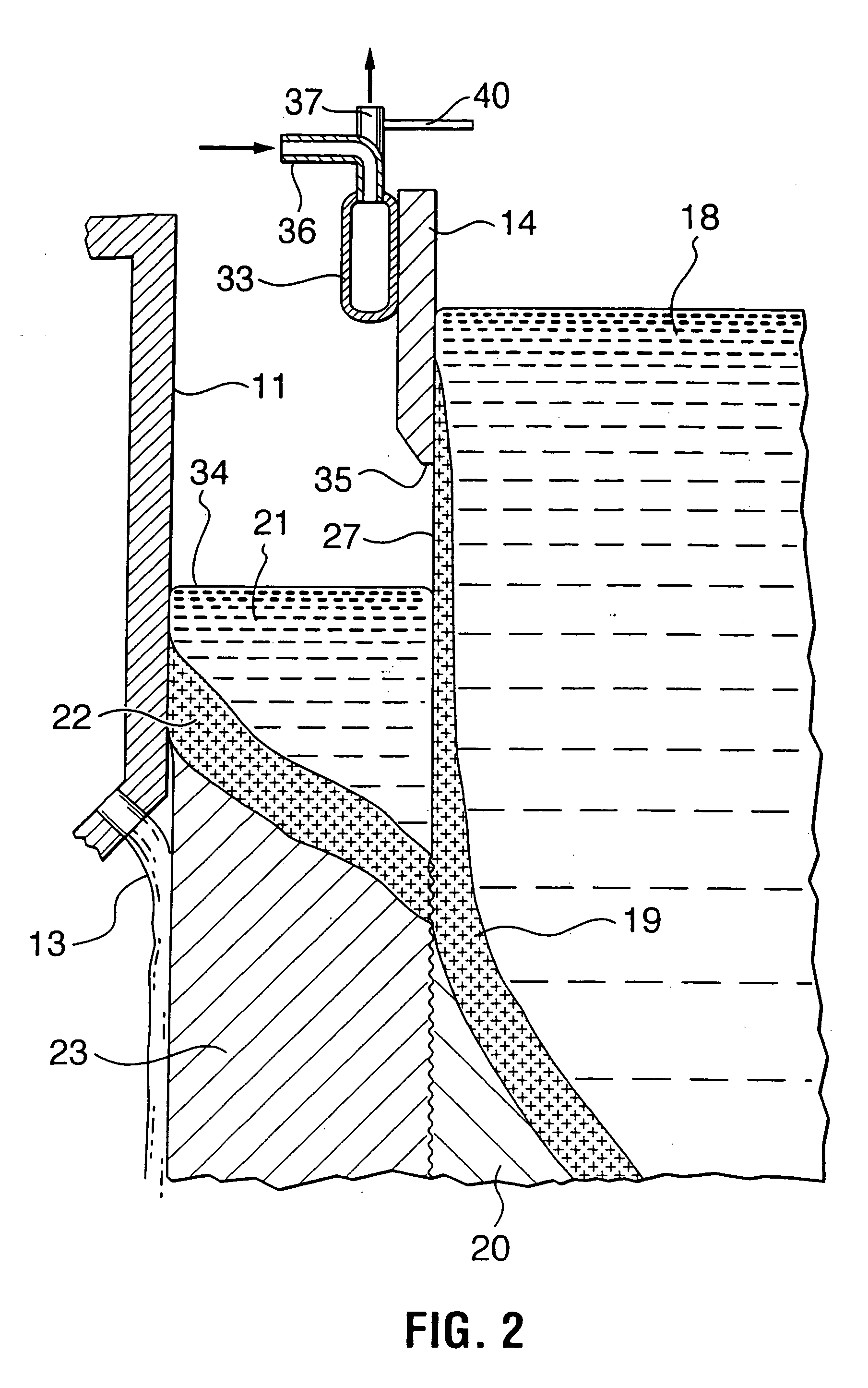
The present invention relates to a method for casting a composite metal ingot with at least two layers formed of different alloys compositions. The method involves using divider walls to separate the feed end of the mould into at least two separate feed chambers, each containing one or more alloy streams. The first and second alloy streams are fed to the mould to form two layers of metal in the mould. The first layer is cooled to form a self-supporting surface adjacent to the divider wall. The second alloy stream is brought into contact with the self-supporting surface of the first alloy to form an interface between the two alloys. The interface is then reheated to a temperature between the solidus and liquidus temperatures of the first alloy to join the two alloys as two layers. The method ensures that the interface between the two alloys is maintained at a specific temperature and can control stresses in the finished product.

Problems solved by technology

This has a disadvantage in that the interface between the slabs is generally not metallurgically clean and bonding of the layers can be a problem.
However, the method is not controllable in the sense that the baffle used is “passive” and the casting depends on control of the sump location-which is indirectly controlled by the cooling system.
An important element that inhibits roll-bonding is Mg, so that AA5000 series alloys are difficult to roll-bond to other alloys.

Method used


Image

  • Method for casting composite ingot
  • Method for casting composite ingot
  • Method for casting composite ingot

Examples


examples

[0117]FIG. 13 is a microphotograph at 15.times. magnification showing the interface 80 between an Al—Mn alloy 81 (X-904 containing 0.74% by weight Mn, 0.55% by weight Mg, 0.3% by weight Cu, 0.17% by weight, 0.07% by weight Si and the balance Al and inevitable impurities) and an Al—Si alloy 82 (AA4147 containing 12% by weight Si, 0.19% by weight Mg and the balance Al and inevitable impurities) cast under the conditions of the present invention. The Al—Mn alloy had a solidus temperature of 1190° F. (643° C.) and a liquidus temperature of 1215° F. (657° C.). The Al—Si alloy had a solidus temperature of 1070° F. (576° C.) and a liquidus temperature of 1080° F. (582° C.). The Al—Si alloy was fed into the casting mould such that the upper surface of the metal was maintained so that it contacted the Al—Mn alloy at a location where a self-supporting surface has been established on the Al—Mn alloy, but its temperature was between the solidus and liquidus temperatures of the Al—Mn alloy.

[011...


PUM

PropertyMeasurementUnit
diameteraaaaaaaaaa
diameteraaaaaaaaaa
thickaaaaaaaaaa

Abstract

A method and apparatus for the casting of a composite metal ingot comprising at least two separately formed layers of one or more alloys. An open ended annular mould has a feed end and an exit end and divider wall for dividing the feed end into at least two separate feed chambers, where each feed chamber is adjacent at least one other feed chamber. For each pair of adjacent feed chambers a first alloy stream is fed through one of the pair of feed chambers into the mould and a second alloy stream is fed through another of the feed chambers. A self-supporting surface is generated on the surface of the first alloy stream and the second alloy stream is contacted with the first stream such that the upper surface of the second alloy stream is maintained at a position such that it first contacts the self-supporting surface where the self-supporting surface temperature is between the liquidus and solidus temperatures of the first alloy or it first contacts the self-supporting surface where the self-supporting surface temperature is below the solidus temperatures of the first alloy but the interface between the two alloys is then reheated to between the liquidus and solidus temperatures, whereby the two alloy streams are joined as two layers. The joined alloy layers are then cooled to form a composite ingot. This composite ingot has a substantially continuous metallurgical bond between alloy layers with dispersed particles of one or more intermetallic compositions of the first alloy in a region of the second alloy adjacent the interface. The combination of an alloy of high strength bonded to a surface layer of higher ductility gives a sheet of improved bendability compared to the high strength alloy used alone.

Description

CROSS-REFERENCE TO RELATED APPLICATION [0001] This application is a continuation-in-part of our prior U.S. application Ser. No. 10 / 875,978 filed Jun. 23, 2004 which claims the benefit of U.S. Provisional Application Ser. No. 60 / 482,229, filed Jun. 24, 2003, both of which are incorporated herein by this reference.FIELD OF THE INVENTION [0002] This invention relates to a method and apparatus for casting composite metal ingots, as well as novel composite metal ingots thus obtained. BACKGROUND OF THE INVENTION [0003] For many years metal ingots, particularly aluminum or aluminum alloy ingots, have been produced by a semi-continuous casting process known as direct chill casting. In this procedure molten metal has been poured into the top of an open ended mould and a coolant, typically water, has been applied directly to the solidifying surface of the metal as it emerges from the mould. [0004] Such a system is commonly used to produce large rectangular-section ingots for the production of...

Claims


Application Information

Patent Timeline
Patent Type & Authority Applications(United States)
IPC IPC(8): B22D11/00B22D11/049B22D11/10B22D11/103
CPCB22D11/007B22D11/103Y10T428/26Y10T428/12493Y10T428/12764Y10T428/12736Y10T428/12451Y10T428/264Y10T428/12222Y10T428/12472B22D11/00B22D7/02
Inventor ANDERSON, MARK DOUGLASKUBO, KENNETH TAKEOBISCHOFF, TODD F.FENTON, WAYNE J.REEVES, ERIC W.SPENDLOVE, BRENTWAGSTAFF, ROBERT BRUCEBULL, MICHAEL J.LLOYD, DAVID J.EVANS, DANIEL
Owner NOVELIS INC
Learn More