Underground drilling device employing down-hole radar

a technology of radar and drilling device, applied in the direction of directional drilling, borehole/well accessories, survey, etc., can solve the problems of affecting the original condition of structures or roadways, damage to previously buried utilities, and structures or roadways disturbed by digging trenches. rarely restored to their original condition

Inactive Publication Date: 2006-08-24
VERMEER MFG CO
View PDF4 Cites 56 Cited by
  • Summary
  • Abstract
  • Description
  • Claims
  • Application Information

AI Technical Summary

Problems solved by technology

In areas supporting existing construction, a trench can cause serious disturbance to structures or roadways.
Further, there is a high probability that digging a trench may damage previously buried utilities, and that structures or roadways disturbed by digging the trench are rarely restored to their original condition.
Also, an open trench poses a danger of injury to workers and passersby.
It can be appreciated that present methods of detecting and controlling boring tool movement along a desired underground path is cumbersome, fraught with inaccuracies, and require repeated halting of boring operations.
Moreover, the inherent delay resulting from verbal communication of course change instructions between the operator of the locator and the boring machine operator may compromise tunneling ...

Method used


Image

  • Underground drilling device employing down-hole radar
  • Underground drilling device employing down-hole radar
  • Underground drilling device employing down-hole radar

Examples


first embodiment

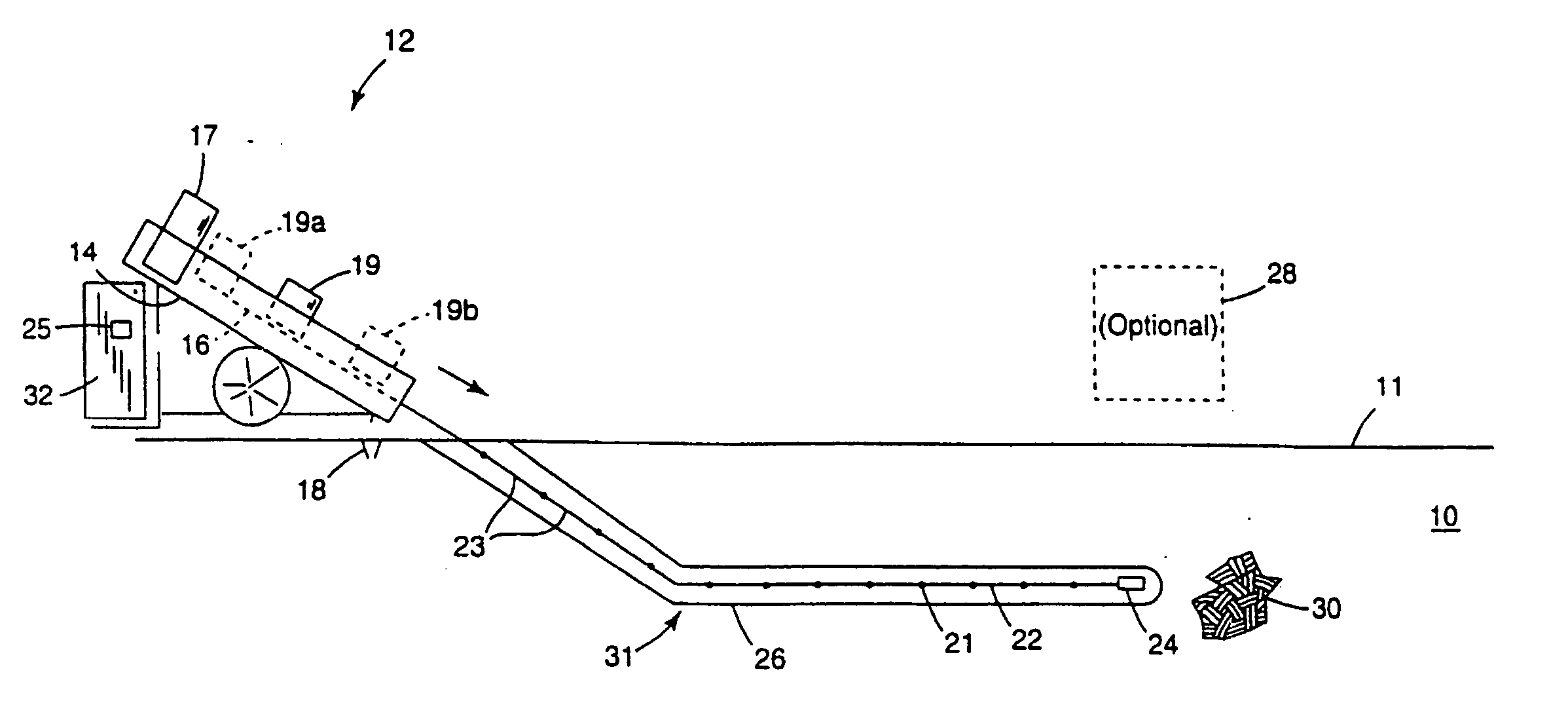
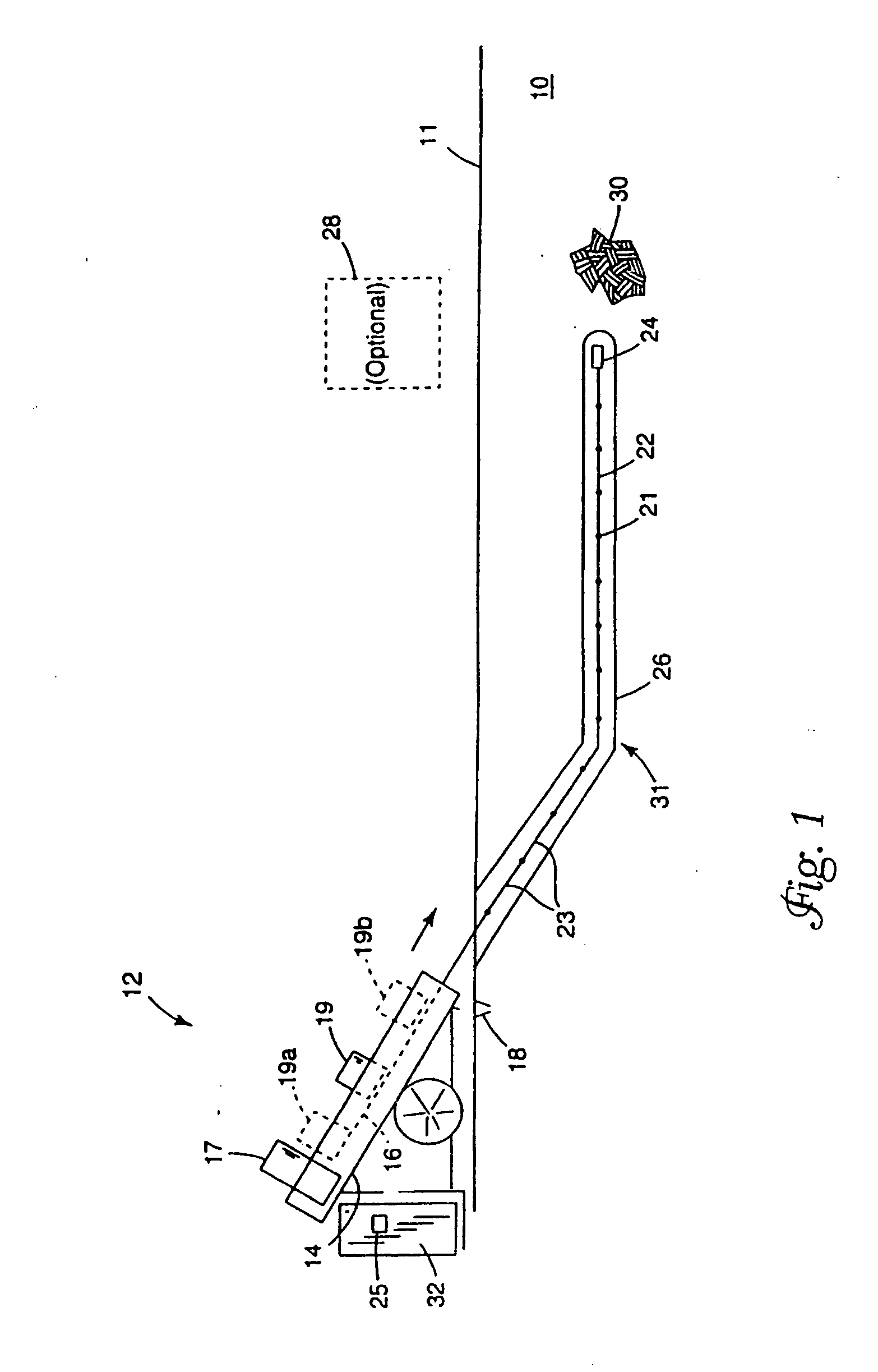
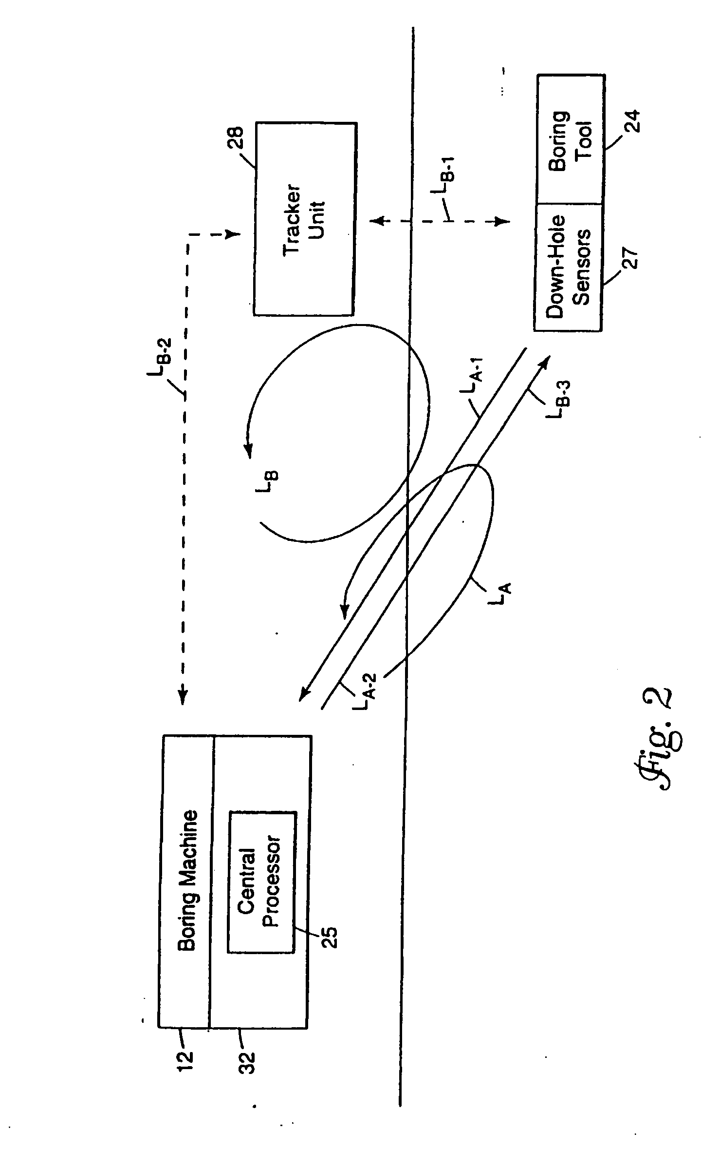
[0066]FIG. 2 illustrates an important aspect of the present invention. In particular, FIG. 2 depicts various embodiments of a closed-loop control system as defined between the boring machine 12 and the boring tool 24. According to one embodiment, communication of information between the boring machine 12 and the boring tool 24 is facilitated via the drill string. A control loop, LA, illustrates the general flow of information through a closed-loop boring control system according to the present invention. The down-hole sensor unit 27 provided in the boring tool 24 provides location and orientation data. The acquired data may be processed locally within the down-hole sensor unit 27. The data acquired at the boring tool 24 is transmitted as an information signal along a first loop segment, LA-1, and is received by the boring machine 12. The received information signal is processed by the central processor 25 typically provided in a control unit 32 of the boring machine 12. Control sign...

second embodiment

[0068] In accordance with a second embodiment, a closed-loop control system is defined between the boring machine 12, boring tool 24, and tracker unit 28. A control loop, LB, illustrates the general flow of information through this embodiment of a closed-loop control system of the present invention. The boring tool 24 transmits an information signal along a first loop segment, LB-1, which is received by the tracker unit 28. In response to the received information signal, the tracker unit 28 transmits an information signal along a second loop segment, LB-2, which is received by the central processor 25. The received information signal is processed by the central processor 25 of the boring machine 12. In response to the processed information signal, desired adjustments are made by the boring machine 12 to alter or maintain the activity of the boring tool 24, such adjustments being effected along a third loop segment, LB-3, of the control loop, LB. It is noted that the first and second...


PUM


Abstract

Devices for sensing at an underground drilling device in communication with an above-ground locator involve transmitting a radar probe signal from the underground drilling device. A radar return signal is received at the underground drilling device. The radar return signal is processed at the underground drilling device to produce sensor data. The sensor data is transmitted in a form suitable for reception by the above-ground locator.

Description

[0001] This is a divisional of Ser. No. 10 / 878,074, filed Jun. 28, 2004, which is a continuation of Ser. No. 10 / 283,006, filed Oct. 29, 2002, now U.S. Pat. No. 6,755,263, which is a divisional of Ser. No. 09 / 955,675, filed Sep. 19, 2001, now U.S. Pat. No. 6,470,976, which is a divisional of Ser. No. 09 / 405,889, filed Sep. 24, 1999, now U.S. Pat. No. 6,308,787, which are hereby incorporated by reference herein.BACKGROUND OF THE INVENTION [0002] The present invention relates generally to the field of underground boring and, more particularly, to underground sensing at a cutting tool using down-hole radar. [0003] Utility lines for water, electricity, gas, telephone and cable television are often run underground for reasons of safety and aesthetics. In many situations, the underground utilities can be buried in a trench which is then back-filled. Although useful in areas of new construction, the burial of utilities in a trench has certain disadvantages. In areas supporting existing cons...

Claims


Application Information

Patent Timeline
IPC IPC(8): E21B44/00E21B7/04E21B7/26E21B47/022
CPCE21B7/06E21B7/065E21B7/265E21B44/00E21B47/02224E21B47/0232
Inventor ALFT, KEVINBISCHEL, BRIAN J.AUSTIN, GREGG A.KELPE, HANS
Owner VERMEER MFG CO
Why Eureka
Try Eureka