Damping valve

Inactive Publication Date: 2006-08-24
ZF FRIEDRICHSHAFEN AG
View PDF10 Cites 19 Cited by
  • Summary
  • Abstract
  • Description
  • Claims
  • Application Information

AI Technical Summary

Benefits of technology

[0009] The object of the present invention is to realize a multi-stage damping valve which makes it possible to produ

Problems solved by technology

In both of the documents cited above, the problem is that the valve seating surfaces for the additional valve must be manufactured with extreme precision so that even the smallest leak is avoided.
If one were simply t

Method used


Image

  • Damping valve
  • Damping valve
  • Damping valve

Examples


Embodiment Construction

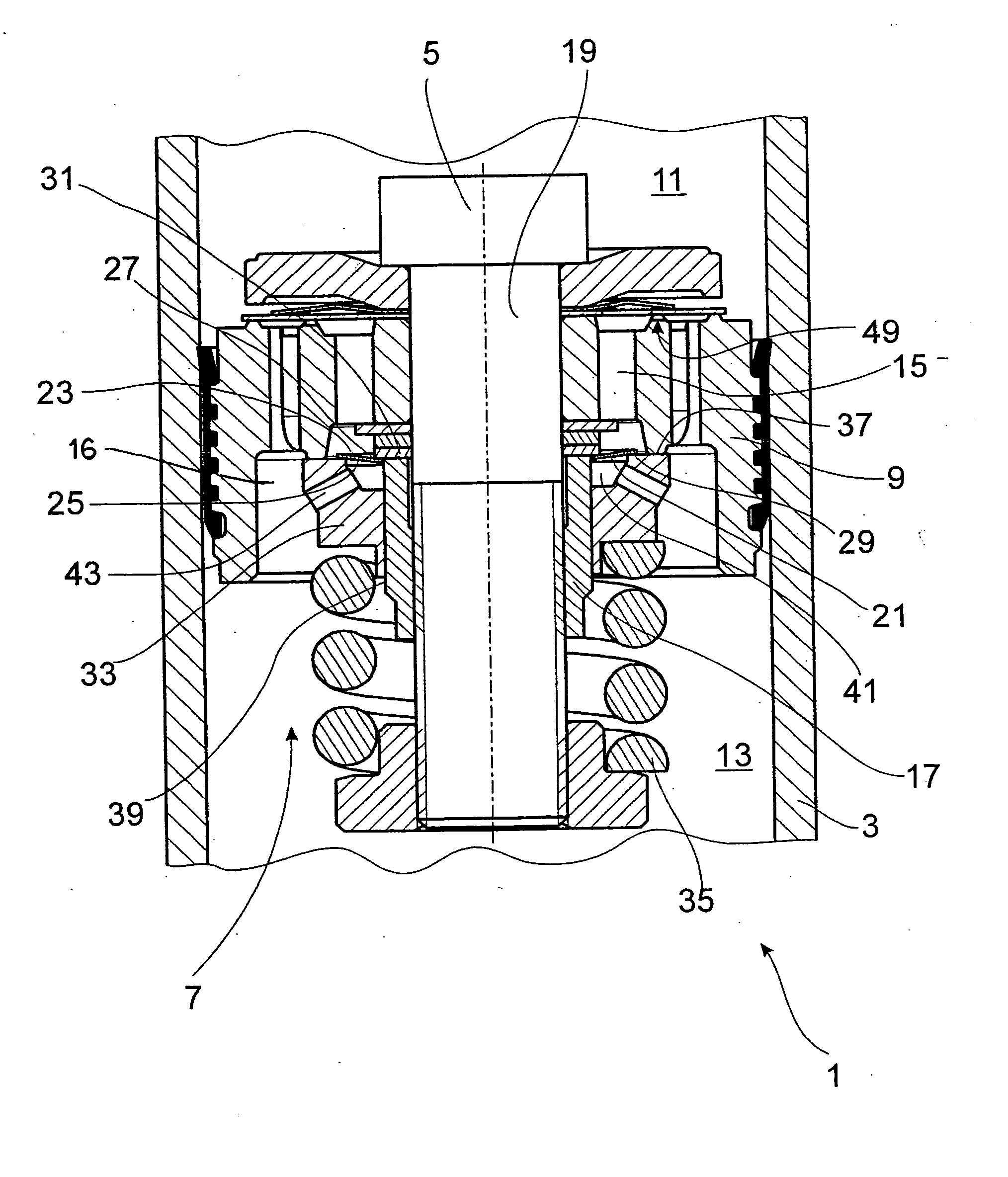
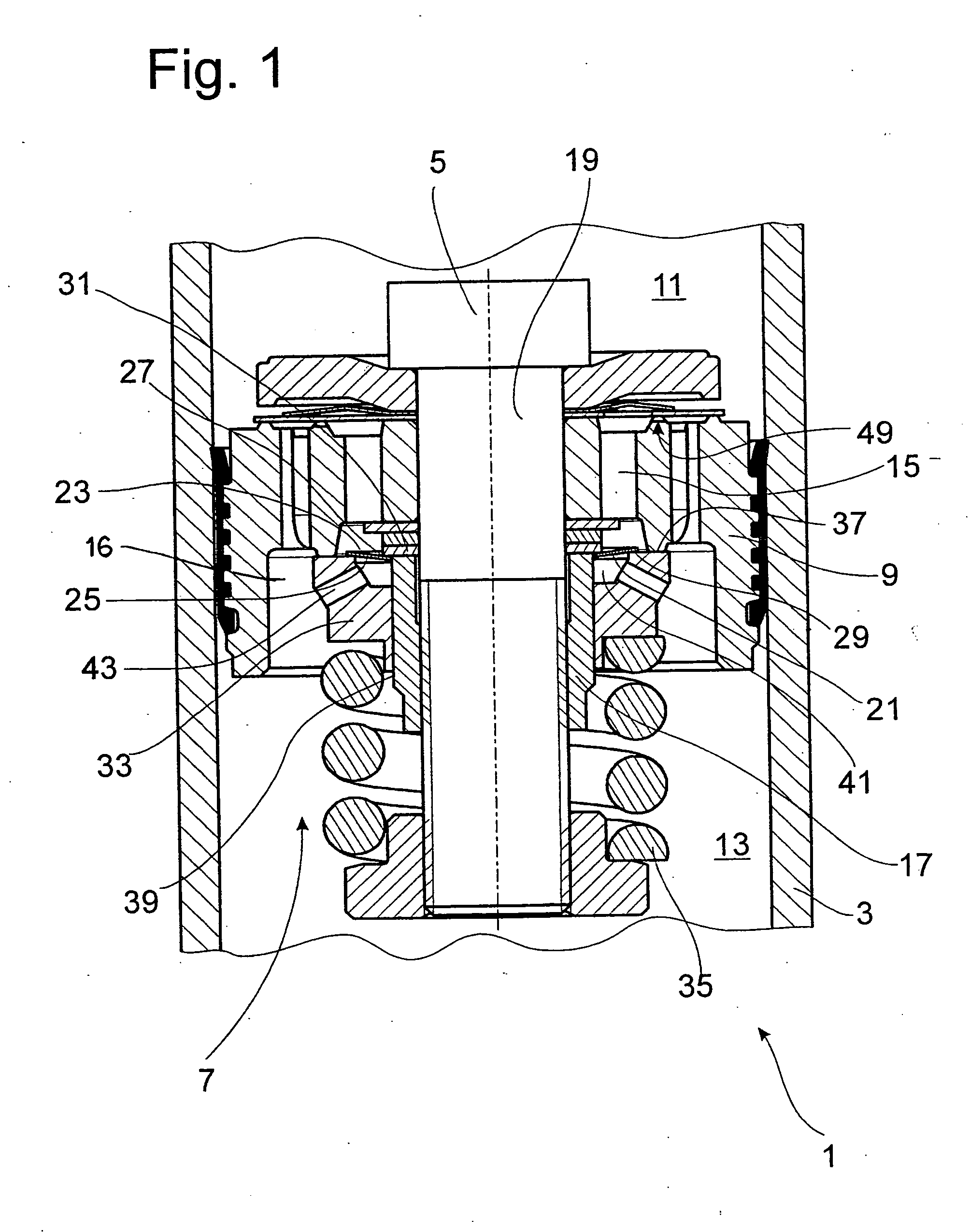
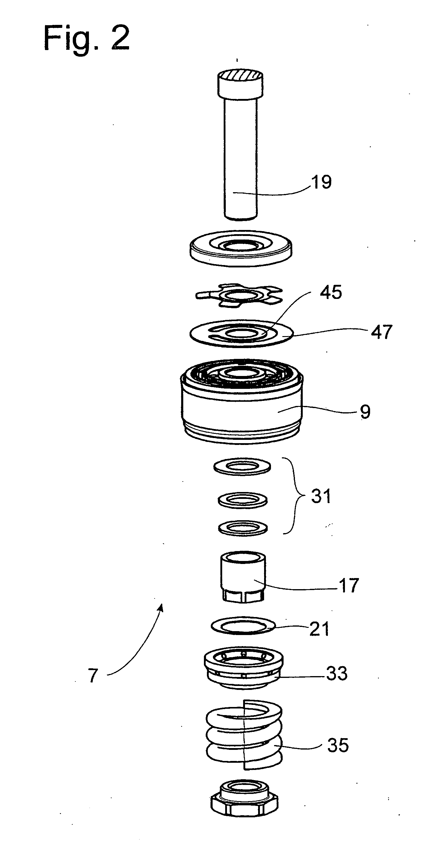
[0026]FIG. 1 shows part of a vibration damper 1, such as that used in a motor vehicle. A piston rod 5 with a damping valve device 7 in the form of a piston is installed with freedom of axial movement in a cylinder 3. An exploded view of the damping valve device 7 is shown in FIG. 2. A damping valve body 9 divides the cylinder 3 into a working space 11 on the piston rod-side of the piston and a working space 13 on the side of the piston opposite the piston rod. At least one flow channel 15 is provided inside the damping valve body 9; one end of this channel is connected without a throttling effect to the working space 11 on the piston rod side. A piston nut 17 holds the damping valve piston in place on a piston rod pin 19.

[0027] The end of the flow channel facing the working space 13 on the side of the piston opposite the piston rod is at least partially closed by a first spring-loaded valve disk 21. The spring-loading is produced by the tensioning of the valve disk 21 between a fir...


PUM


Abstract

Damping valve device having a damping valve body with at least one flow channel, which is closed at least partially by a first spring-loaded valve disk on a first valve seating surface, and a second spring-loaded valve disk, which rises from its valve seat at a higher opening pressure than the first valve disk. One of the cover sides of the first spring-loaded valve disk is held under tension on the first valve seating surface while the other cover side is held under tension on a second valve seating surface, and one of the valve seating surfaces of the first valve disk executes a lifting movement synchronously with the second spring-loaded valve disk.

Description

BACKGROUND OF THE INVENTION [0001] 1. Field of the Invention [0002] The invention pertains to a damping valve having a valve body with a flow channel which is closed by a first spring loaded valve disk and a second spring loaded valve disk which rises from its seat at a higher opening pressure than the first disk. [0003] 2. Description of the Related Art [0004] Damping valves for vibration dampers often have a so-called “pilot” cross section, which is formed by, for example, a small aperture in a valve disk. Small volume flow rates, which occur during the movement of the piston rod, flow completely through the pilot cross section and generate a comparatively small damping force. As soon as the velocity of the piston rod exceeds a certain value, however, a valve disk rises from a valve seat and releases a cross section which is much larger than the pilot cross section. The closing forces acting on the valve disk, which are introduced by at least one spring, are carefully coordinated ...

Claims


Application Information

Patent Timeline
IPC IPC(8): F16F9/348
CPCF16F9/3485F16F9/516
Inventor SCHMITT, STEFAN
Owner ZF FRIEDRICHSHAFEN AG
Why Eureka
Try Eureka