Panel for slim cathode ray tubes

a cathode ray tube and panel technology, applied in the field of cathode ray tube panel size, can solve the problems of increased manufacturing cost of the panel b>1/b>, easy slippage of the reinforcing band b>11/b>, increased volume of the panel, etc., to achieve the effect of reducing the overall length of the tube, and sufficient rigidity

Inactive Publication Date: 2006-08-24
MERIDIAN SOLAR & DISPLAY
View PDF6 Cites 0 Cited by
  • Summary
  • Abstract
  • Description
  • Claims
  • Application Information

AI Technical Summary

Benefits of technology

[0039] According to the present invention, the thickness of the center of the panel, and the thicknesses of the long side, the short side, and the diagonal part of the seal edge are appropriately set so as to uniformly distribute the stress locally concentrated on the tube part due to the increase of the deflection angle. Consequently, the present invention has the effect of improving the explosion-resistance characteristic and providing sufficient rigidity even through the overall length of the tube part is reduced.
[0040] Also, the thickness of the seal edge of the panel is appropriately set according to the present invention. Consequently, damage to the panel is prevented during the production of the tube part, and the implosion rule is satisfied.
[0041] Furthermore, the outer skirt angle of the panel is set to 0.5 to 1.5 degrees, and the outer skirt angle of the panel is set such that the following inequality is satisfied: the outer skirt angle at the short side>the outer skirt angle at the diagonal part>the outer skirt angle at the long side. As a result, the vacuum stress is uniformly distributed. Consequently, the explosion-resistance characteristic and moldability of the panel are improved, and slippage of the reinforcing band is effectively prevented.

Problems solved by technology

However, the total volume of the panel 1 is increased, and therefore, manufacturing costs of the panel 1 are also increased.
When the outer skirt angle S of the panel 1 is large as described above, however, the reinforcing band 11 can easily slip.
Consequently, it is difficult to perform the reinforcing band winding process, and it is difficult to effectively distribute stress applied to the tube part 10 when the reinforcing band 11 slips.

Method used


Image

  • Panel for slim cathode ray tubes
  • Panel for slim cathode ray tubes
  • Panel for slim cathode ray tubes

Examples


Embodiment Construction

[0052] Now, a preferred embodiment of the present invention will be described in detail with reference to the accompanying drawings.

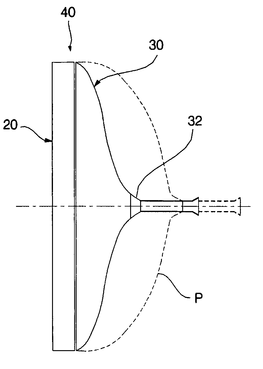
[0053]FIG. 6 is a side view schematically illustrating a cathode ray tube to which a panel according to the present invention is applied.

[0054] Preferably, the panel according to the present invention is applied to a slim cathode ray tube having a deflection angle of 110 degrees of more.

[0055] The slim cathode ray tube shown in FIG. 6 has a deflection angle of 110 degrees or more. Also, the slim cathode ray tube includes a tube part 40, the overall length of which is 350 mm or less. The overall length of the tube part 40, which is formed by joining a panel 20 and a funnel 30 with each other, is less than that of a tube part P of a conventional cathode ray tube, which is shown in FIG. 6 by a dotted line.

[0056] The size of the funnel 30 of the slim cathode ray tube is remarkably reduced as compared to the size of the funnel of the conventional cathode...


PUM


Abstract

Disclosed herein is a panel of a slim cathode ray tube constructed such that the deflection angle of an electron beam is 110 degrees or more. The slim cathode ray tube includes a tube part constituted by joining the panel and a funnel with each other. The panel includes a face part, a side wall disposed around the face part such that the side wall is bent toward the funnel, and a seal edge formed at the side wall, the panel being joined with the funnel at the seal edge. On the assumption that the thickness of the center of the face part is Tc, the thickness of the long side of the seal edge is Tx, the thickness of the short side of the seal edge is Ty, and the thickness of the diagonal part of the seal edge is Td, the panel is constructed such that the following inequalities are satisfied: 0.8≦Tc/Ty≦Tc/Tx≦1.0≦Tc/Td and Td<Tx<Ty, and the side wall has an outer skirt angle of 0.5 to 1.5 degrees.

Description

BACKGROUND OF THE INVENTION [0001] 1. Field of the Invention [0002] The present invention relates to a slim cathode ray tube, and, more particularly, to a panel for color cathode ray tubes wherein the thickness of the center of the panel, and the thicknesses of a seal edge are appropriately set, and the outer skirt angle of the panel is appropriately set, thereby minimizing the concentration of stress caused due to the increase of a deflection angle, providing sufficient rigidity, improving the explosion-resistance characteristic and moldability of the panel, and effectively preventing slippage of a reinforcing band. [0003] 2. Description of the Related Art [0004] Generally, a cathode ray tube is an apparatus that converts an electric signal into an electron beam and scans the electron beam on a fluorescent screen to display picture on a panel. [0005]FIG. 1 is a side view, partially cut away, illustrating a conventional cathode ray tube, and FIG. 2 is a sectional view illustrating a...

Claims


Application Information

Patent Timeline
Patent Type & Authority Applications(United States)
IPC IPC(8): H01J29/10
CPCH01J29/86H01J2229/8606
Inventor HONG, BYONG GYUCHOI, SAM KIKIM, YOUNG WOONG
Owner MERIDIAN SOLAR & DISPLAY
Why Eureka
Try Eureka