Funnel for slim cathode ray tubes

a cathode ray tube and funnel technology, applied in the direction of cathode ray/electron beam tube electrical connection, discharge tube luminescnet screen, discharge tube, etc., can solve the problem of structurally difficult to reduce the length of the yoke part, and achieve the effect of reducing the overall length of the tube part, preventing stress from being concentrated, and improving the explosion resistance characteristic of the funnel

Inactive Publication Date: 2009-01-27
MERIDIAN SOLAR & DISPLAY
View PDF2 Cites 0 Cited by
  • Summary
  • Abstract
  • Description
  • Claims
  • Application Information

AI Technical Summary

Benefits of technology

[0015]Therefore, the present invention has been made in view of the above problems, and it is an object of the present invention to provide a funnel for slim cathode ray tubes wherein the thickness of a body of the funnel and the thickness, the curvature, and the angle of a top of round (TOR) part of the funnel to prevent stress from being concentrated due to the reduction in overall length of a tube part, whereby the explosion-resistance characteristic of the funnel is improved.
[0029]According to the present invention, the thickness of the body of the funnel for slim cathode ray tubes and the thickness, the curvature, and the angle of the TOR part of the funnel are appropriately designed to prevent stress from being concentrated due to the reduction in overall length of the tube part. Consequently, the present invention has the effect of improving the explosion-resistance characteristic of the funnel and producing a functional screen while satisfying BSN / YPB.

Problems solved by technology

Especially in the case of the funnel 2, it is structurally difficult to reduce the length of the yoke part 2y, at which the deflection yoke is mounted.

Method used


Image

  • Funnel for slim cathode ray tubes
  • Funnel for slim cathode ray tubes
  • Funnel for slim cathode ray tubes

Examples


Embodiment Construction

[0038]Now, a preferred embodiment of the present invention will be described in detail with reference to the accompanying drawings.

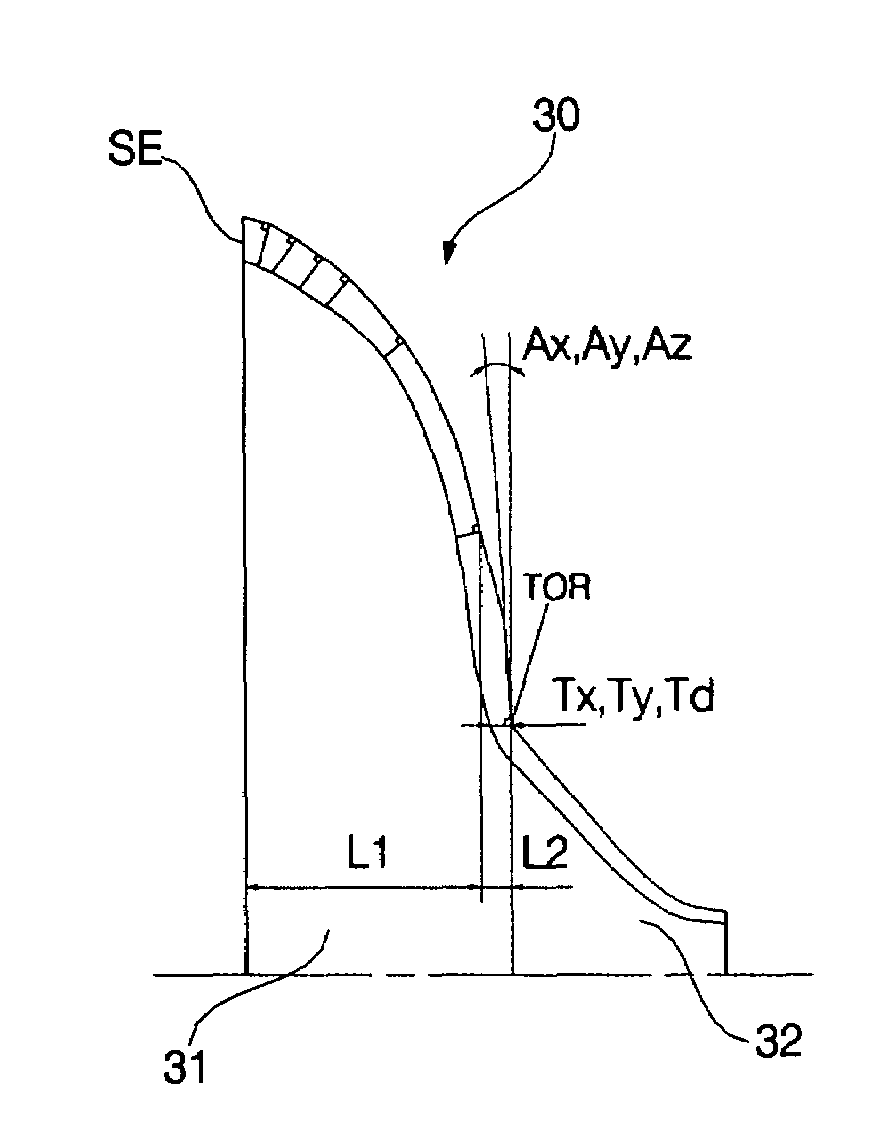
[0039]FIG. 4 is a front view illustrating a funnel 30 for slim cathode ray tubes according to the present invention, FIG. 5 is an enlarged view illustrating a top of round (TOR) part of the funnel 30 shown in FIG. 4, and FIG. 6 is a side view illustrating the funnel 30 for slim cathode ray tubes according to the present invention.

[0040]As shown in FIGS. 4 to 6, the funnel 30 according to the present invention is applied to a slim cathode ray tube wherein the deflection angle of an electron beam is 120 degrees or more and the overall length of the tube, which is formed by joining a panel (not shown) and the funnel 30 to each other, is considerably less than that of a conventional cathode ray tube.

[0041]The funnel 30 includes a body 31 and a yoke part 32, which are separated from each other about a top of round (TOR) part. The body 31 is a part extending f...


PUM


Abstract

Disclosed herein is a funnel for slim cathode ray tubes. The funnel is constructed such that the deflection angle of an electron beam is 120 degrees or more. On the assumption that, at a top of round (TOR) part located between a body and a yoke part, the thickness of each long side (x-axis) is Tx, the thickness of each short side (y-axis) is Ty, and the thickness of each diagonal part is Td, the following inequality is satisfied: Td>Tx>Ty. The TOR part has a horizontal inner curvature, a horizontal outer curvature, and a vertical outer curvature, which are convex toward the outside of the funnel, and a vertical inner curvature, which is convex toward the inside of the funnel. On the assumption that, at the body from a seal edge, at which the body is joined with a panel, to the TOR part, the thickness of each long side (x-axis) is Bx, the thickness of each short side (y-axis) is By, and the thickness of each diagonal part is Bd, the thickness ratio of the body from the seal edge to the ⅔ point of the body is set such that the following inequality is satisfied: Bx>By>Bd.

Description

BACKGROUND OF THE INVENTION[0001]1. Field of the Invention[0002]The present invention relates to a funnel for slim cathode ray tubes, and, more particularly, to a funnel for color cathode ray tubes constructed such that stress is prevented from being concentrated on the funnel when a deflection angle is 110 degrees or more.[0003]2. Description of the Related Art[0004]FIG. 1 is a side view, partially cut away, illustrating a conventional cathode ray tube. As shown in FIG. 1, the conventional cathode ray tube comprises a panel 1 and a funnel 2, which are joined with each other to constitute a tube part 10.[0005]Inside the panel 1 is disposed a shadow mask 3, which is supported by a frame 4 such that the shadow mask 3 is approximately parallel with the panel 1. The frame 4 is fixed to the panel 1 via a spring 5. Inside the funnel 2 is disposed an inner shield 6 for shielding an external geomagnetic field to prevent the path of an electron beam from being curved by the external geomagne...

Claims


Application Information

Patent Timeline
Patent Type & Authority Patents(United States)
IPC IPC(8): H01J1/62
CPCH01J29/861H01J29/87H01J2229/8606H01J2229/862
Inventor HWANG, YONG IK
Owner MERIDIAN SOLAR & DISPLAY
Why Eureka
Try Eureka