Movable barrier operator

a technology of operator and moving barrier, which is applied in the direction of motor/generator/converter stopper, dynamo-electric converter control, instruments, etc., can solve the problems of high impulse force application, and achieve the effect of less momentum and soft, smooth and quiet stop

Inactive Publication Date: 2006-08-24
THE CHAMBERLAIN GRP INC
View PDF6 Cites 6 Cited by
  • Summary
  • Abstract
  • Description
  • Claims
  • Application Information

AI Technical Summary

Benefits of technology

[0016] A movable barrier operator having an electric motor for driving a garage door, a gate or other barrier is operated from a source of AC current. The movable barrier operator includes circuitry for automatically detecting the incoming AC line voltage and frequency of the alternating current. By automatically detecting the incoming AC line voltage and determining the frequency, the operator can automatically configure itself to certain user preferences. This occurs without either the user or the installer having to adjust or program the operator. The movable barrier operator includes a worklight for illuminating its immediate surroundings such as the interior of a garage. The barrier operator senses the power line frequency (typically 50 Hz or 60 Hz) to automatically set an appropriate shut-off time for a worklight. Because the power line frequency in Europe is 50 Hz and in the U.S. is 60 Hz, sensing the power line frequency enables the operator to configure itself for either a European or a U.S. market with no user or installer modifications. For U.S. users, the worklight shut-off time is set to preferably 4½ minutes; for European users, the worklight shut-off time is set to preferably 2½ minutes. Thus, a single barrier movement operator can be sold in two different markets with automatic setup, saving installation time.
[0017] The movable barrier operator of the present invention automatically detects if an optional flasher module is present. If the module is present, when the door is commanded to move, the operator causes the flasher module to operate. With the flasher module present, the operator also delays operation of the motor for a brief period, say one or two seconds. This delay period with the flasher module blinking before door movement provides an added safety feature to users which warns them of impending door travel (e.g. if activated by an unseen transmitter).
[0018] The movable barrier operator of the present invention drives the barrier, which may be a door or a gate, at a variable speed. After motor start, the electric motor reaches a preferred initial speed of 20 percent of the full operating speed. The motor speed then increases slowly in a linearly continuous fashion from 20 percent to 100 percent of full operating speed. This provides a smooth, soft start without jarring the transmission or the door or gate. The motor moves the barrier at maximum speed for the largest portion of its travel, after which the operator slowly decreases speed from 100 percent to 20 percent as the barrier approaches the limit of travel, providing a soft, smooth and quiet stop. A slow, smooth start and stop provides a safer barrier movement operator for the user because there is less momentum to apply an impulse force in the event of an obstruction. In a fast system, relatively high momentum of the door changes to zero at the obstruction before the system can actually detect the obstruction. This leads to the application of a high impulse force. With the system of the invention, a slower stop speed means the system has less momentum to overcome, and therefore a softer, more forgiving force reversal. A slow, smooth start and stop also provide a more aesthetically pleasing effect to the user, and when coupled with a quieter DC motor, a barrier movement operator which operates very quietly.
[0019] The operator includes two relays and a pair of field effect transistors (FETs) for controlling the motor. The relays are used to control direction of travel. The FET's, with phase controlled, pulse width modulation, control start up and speed. Speed is responsive to the duration of the pulses applied to the FETs. A longer pulse causes the FETs to be on longer causing the barrier speed to increase. Shorter pulses result in a slower speed. This provides a very fine ramp control and more gentle starts and stops.
[0021] The movable barrier operator provides full door or gate closure, i.e., a firm closure of the door to the floor so that the door is not movable in place after it stops. The operator includes a digital control or processor, specifically a microcontroller which has an internal microprocessor, an internal RAM and an internal ROM and an external EEPROM. The microcontroller executes instructions stored in its internal ROM and provides motor direction control signals to the relays and speed control signals to the FETs. The operator is first operated in a learn mode to store a DOWN limit position for the door. The DOWN limit position of the door is used as an approximation of the location of the floor (or as a minimum reversal point, below which no auto-reverse will occur). When the door reaches the DOWN limit position, the microcontroller causes the electric motor to drive the door past the DOWN limit a small distance, say for one or two inches. This causes the door to close solidly on the floor.
[0022] The operator embodying the present invention provides variable door or gate output speed, i.e., the user can vary the minimum speed at which the motor starts and stops the door. This enables the user to overcome differences in door installations, i.e., stickiness and resistance to movement and other varying functional-type forces. The minimum barrier speeds in the UP and DOWN directions are determined by the user-configured force settings, which are adjusted using UP and DOWN force potentiometers. The force potentiometers set the lengths of the pulses to the FETs, which translate to variable speeds. The user gains a greater force output and a higher minimum starting speed to overcome differences in door installations, i.e., stickiness and resistance to movement and other varying functional-type forces speed, without affecting the maximum speed of travel for the door. The user can configure the door to start at a speed greater than a default value, say 20 percent. This greater start up and slow down speed is transferred to the linearly variable speed function in that instead of traveling at 20 percent speed, increasing to 100 percent speed, then decreasing to 20 percent speed, the door may, for instance, travel at 40 percent speed to 100 percent speed and back down to 40 percent speed.

Problems solved by technology

This leads to the application of a high impulse force.

Method used


Image

  • Movable barrier operator
  • Movable barrier operator
  • Movable barrier operator

Examples


Embodiment Construction

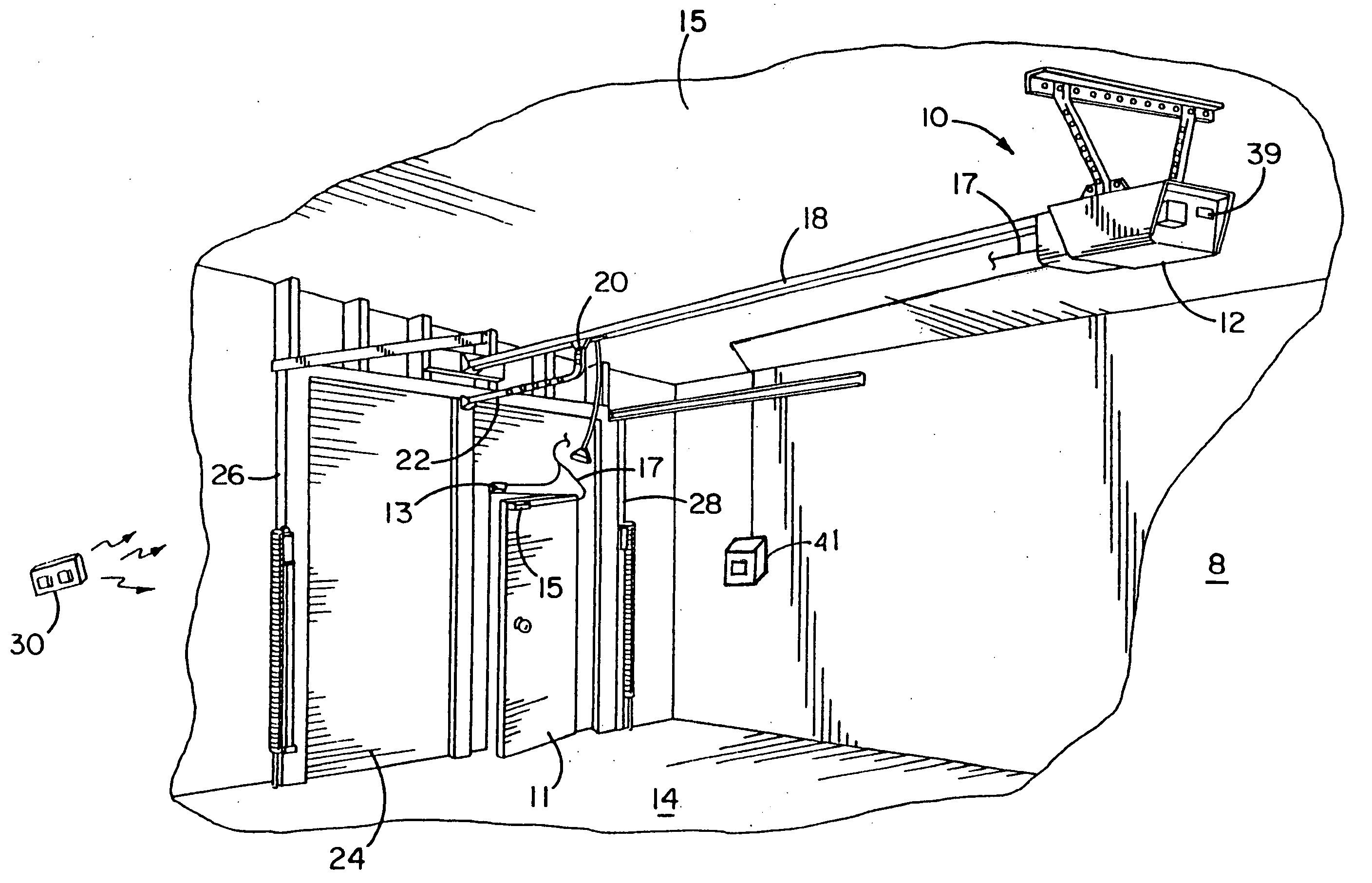
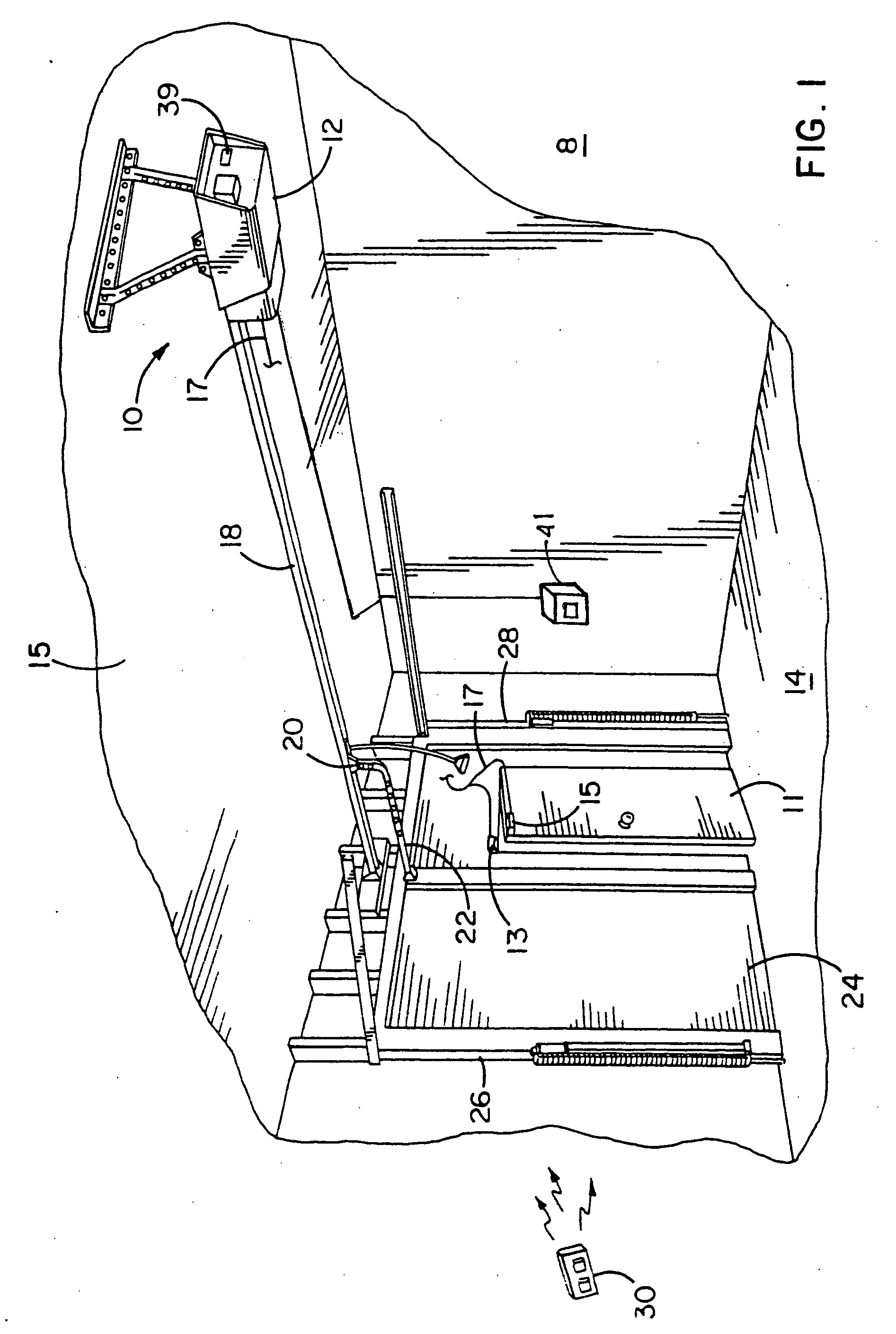
[0046] Referring now to the drawings and especially to FIG. 1, a movable barrier or garage door operator system is generally shown therein and referred to by numeral 8. The system 8 includes a movable barrier operator or garage door operator 10 having a head unit 12 mounted within a garage 14. More specifically, the head unit 12 is mounted to a ceiling 15 of the garage 14. The operator 10 includes a transmission 18 extending from the head unit 12 with a releasable trolley 20 attached. The releasable trolley 20 releasably connects an arm 22 extending to a single panel garage door 24 positioned for movement along a pair of door rails 26 and 28.

[0047] The system 8 includes a hand-held RF transmitter unit 30 adapted to send signals to an antenna 32 (see FIG. 4) positioned on the head unit 12 and coupled to a receiver within the head unit 12 as will appear hereinafter. A switch module 39 is mounted on the head unit12. Switch module 39 includes switches for each of the commands available...


PUM


Abstract

A movable barrier operator having an electrical motor responsive to control signals for moving the barrier, a controller to control the barrier movements, and two command apparatuses for generating command inputs, which command apparatuses are located remotely from each other. The first command apparatus is mounted in a location remote from the controller and easily accessible by the users, and the second command apparatus is located close proximity to the controller to be easily accessible by an installer at the time of service.

Description

[0001] This is a continuation of prior application Ser. No. 10 / 609,788 filed Jun. 30, 2003 which is a continuation of Ser. No. 09 / 804,411, filed Mar. 12, 2001, which is a continuation of Ser. No. 09 / 536,055, filed Mar. 27, 2000, now U.S. Pat. No. 6,246,196, which is a divisional application of Ser. No. 09 / 161,840, filed Sep. 28, 1998, now U.S. Pat. No. 6,172,475.[0002] A computer program listing appendix concurrently submitted to the United States Patent and Trademark Office on a Compact Disk named Codelisting.txt. in duplicate is incorporated herewith by reference. BACKGROUND OF THE INVENTION [0003] This invention relates generally to movable barrier operators for operating movable barriers or doors. More particularly, it relates to garage door operators having improved safety and energy efficiency features. [0004] Garage door operators have become more sophisticated over the years providing users with increased convenience and security. However, users continue to desire further im...

Claims


Application Information

Patent Timeline
Patent Type & Authority Applications(United States)
IPC IPC(8): H02P3/00B23Q35/00E05F15/00E05F15/10E05F15/12E05F15/14E05F15/16E05F15/20E05F15/60G05B5/00G05B9/00G05B19/42G05B23/02H02H7/08H02P1/00H02P1/04H02P7/00H05B37/02H05B39/04
CPCE05D15/38E05Y2201/726E05Y2400/452E05Y2400/456E05Y2400/59E05Y2400/822E05F15/684E05F15/00Y10S388/904Y10S388/909E05Y2800/00E05F15/603E05F15/668E05Y2900/106
Inventor FITZGIBBON, JAMES J.WANIS, PAUL E.WILLMOTT, COLIN B.
Owner THE CHAMBERLAIN GRP INC
Why Eureka
Try Eureka