Magnetoresistive sensor with a free layer stabilized by direct coupling to in stack antiferromagnetic layer

a magnetoresistive sensor and free layer technology, applied in the field of current perpendicular to plane (cpp) magnetoresistive sensors, can solve the problems of weakening the magnetostatic coupling between the insulation layer, the thickness of the magnetic layer (bias layer) must be very thick, and the formation of hard bias layers at either side of the sensor is less effective in a cpp sensor. , to achieve the effect of increasing resistance, reducing specular scattering, and increasing resistan

Inactive Publication Date: 2006-08-24
WESTERN DIGITAL TECH INC
View PDF16 Cites 28 Cited by
  • Summary
  • Abstract
  • Description
  • Claims
  • Application Information

AI Technical Summary

Benefits of technology

[0017] The antiferromagnet bias layer, when exchange coupled one of the magnetic layers of the free layer biases the moment of that layer without pinning that magnetic layer. Exchange coupling of the bias layer with the second magnetic layer of the free layer results in increased resistance and decreased specular scattering at the interface of the bias layer and the second magnetic layer.
[0018] This increased resistance and decreased specular scattering at the interface of the bias layer and second free magnetic layer advantageously reduces the negative GMR contribution that would otherwise result from presence of the second magnetic free layer. This advantageously allows the benefits of a synthetic free layer to be achieved without the usual negative effects of the subtractive GMR from the second layer. The present invention also provides excellent uniform free layer biasing across the width of the free layer.

Problems solved by technology

A challenge to constructing a practical CPP GMR sensor is the necessity of having an insulation layer at either side of the sensor.
This insulation layer weakens the magnetostatic coupling between the bias layer and the free layer.
Therefore, traditional hard bias layers, formed at either side of the sensor, are less effective in a CPP sensor.
Unfortunately however, in order to provide significant biasing, the magnetic layer (bias layer) must be very thick.
Unfortunately, such a thick magnetic layer exhibits poor exchange coupling with the AFM layer.
Therefore, the bias structure described above, does not provide strong stable biasing.
This thick bias structure degrades sensor performance in a CPP sensor by increasing parasitic resistance.
In a CIP sensor such a structure would also lead to current shunting.
The thick in stack bias structure also uses a lot of gap thickness resulting in increased bit length and, therefore, to decrease data density.
Another problem confronted by current sensor designs is that as the track width of the sensor decreases, the magnetic properties of the ever smaller free layer become more unstable.
Therefore, prior art biasing structures (whether hard magnetic or in stack) provide insufficient free layer biasing to stabilize the increasingly unstable free layer in such smaller sensors.

Method used


Image

  • Magnetoresistive sensor with a free layer stabilized by direct coupling to in stack antiferromagnetic layer
  • Magnetoresistive sensor with a free layer stabilized by direct coupling to in stack antiferromagnetic layer
  • Magnetoresistive sensor with a free layer stabilized by direct coupling to in stack antiferromagnetic layer

Examples


Embodiment Construction

[0025] The following description is of the best embodiments presently contemplated for carrying out this invention. This description is made for the purpose of illustrating the general principles of this invention and is not meant to limit the inventive concepts claimed herein.

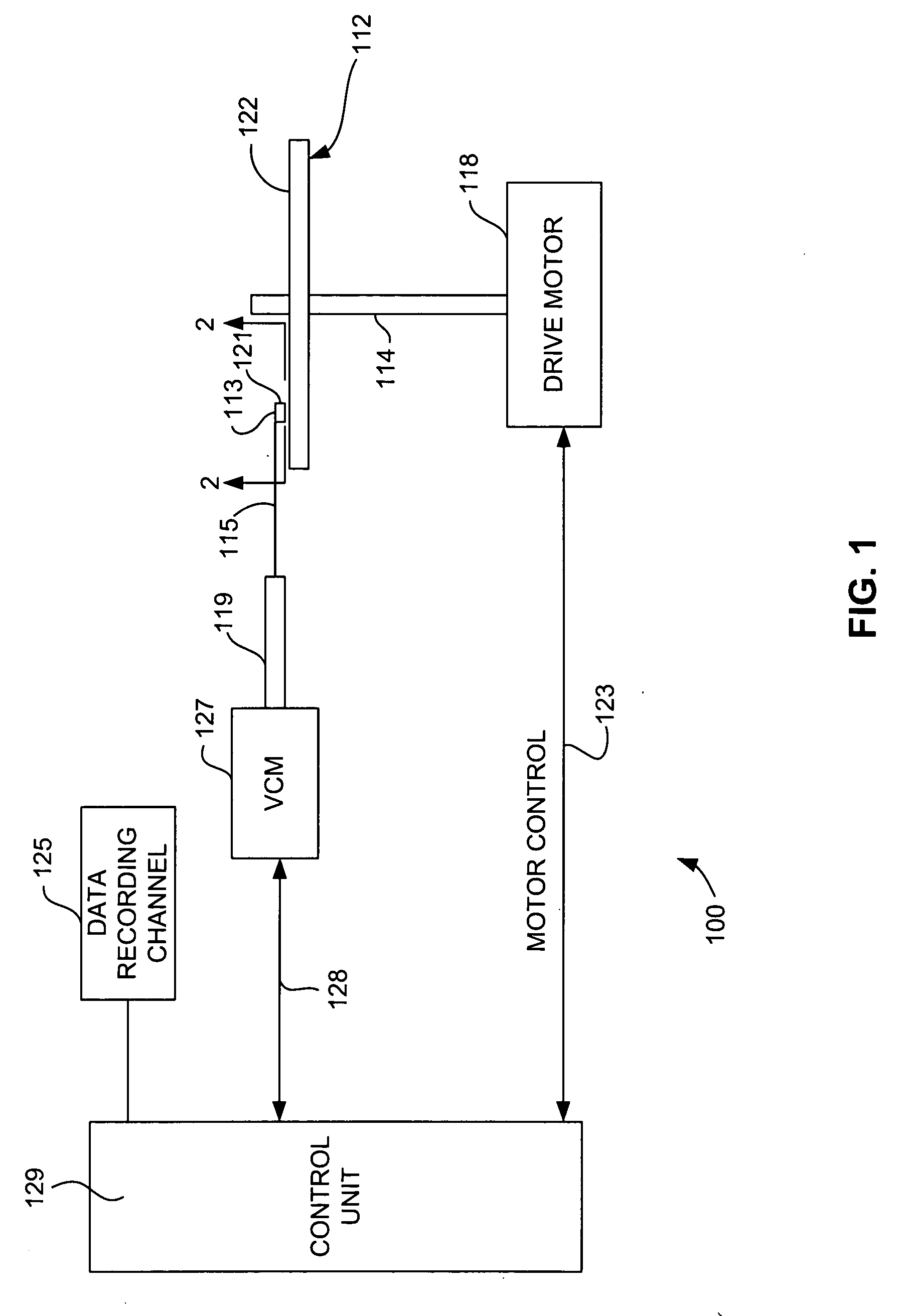
[0026] Referring now to FIG. 1, there is shown a disk drive 100 embodying this invention. As shown in FIG. 1, at least one rotatable magnetic disk 112 is supported on a spindle 114 and rotated by a disk drive motor 118. The magnetic recording on each disk is in the form of annular patterns of concentric data tracks (not shown) on the magnetic disk 112.

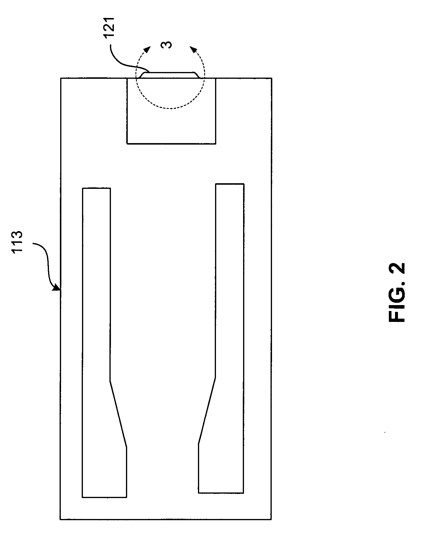
[0027] At least one slider 113 is positioned near the magnetic disk 112, each slider 113 supporting one or more magnetic head assemblies 121. As the magnetic disk rotates, slider 113 moves radially in and out over the disk surface 122 so that the magnetic head assembly 121 may access different tracks of the magnetic disk where desired data are written. Each sli...


PUM

PropertyMeasurementUnit
electrically conductiveaaaaaaaaaa
antiferromagneticaaaaaaaaaa
thicknessaaaaaaaaaa

Abstract

A magnetoresistive sensor having a free layer biased by an in stack bias layer that comprises a layer of antiferromagnetic material. The bias layer can be IrMnCr, IrMn or some other antiferromagnetic material. The free layer is a synthetic free layer having first and second magnetic layers antiparallel coupled across an AP coupling layer. The first magnetic layer is disposed adjacent to a spacer or barrier layer and the second magnetic layer is exchange coupled with the IrMnCr bias layer. The bias layer biases the magnetic moments of the free layer in desired directions parallel with the ABS without pinning the magnetic moments of the free layer.

Description

FIELD OF THE INVENTION [0001] The present invention relates to current perpendicular to plane (CPP) magnetoresistive sensors having a novel in stack free layer bias structure that provides improved free layer stability and decreased sensor thickness. BACKGROUND OF THE INVENTION [0002] The heart of a computer is an assembly that is referred to as a magnetic disk drive. The magnetic disk drive includes a rotating magnetic disk, write and read heads that are suspended by a suspension arm adjacent to a surface of the rotating magnetic disk and an actuator that swings the suspension arm to place the read and write heads over selected circular tracks on the rotating disk. The read and write heads are directly located on a slider that has an air bearing surface (ABS). The suspension arm biases the slider into contact with the surface of the disk when the disk is not rotating but, when the disk rotates, air is swirled by the rotating disk. When the slider rides on the air bearing, the write...

Claims


Application Information

Patent Timeline
Patent Type & Authority Applications(United States)
IPC IPC(8): G11B5/33G11B5/127
CPCG11B5/39
Inventor GILL, HARDAYAL SINGHHO, KUOK SAN
Owner WESTERN DIGITAL TECH INC
Why Eureka
Try Eureka