Power factor correction apparatus

a power factor and power factor technology, applied in the field of power factor correction apparatus, can solve the problems of capacitor cb>1/b> not being fully charged to the peak voltage of the input ac voltage, higher manufacturing cost, delay in charging time of capacitor cb>1/b>, etc., to increase the conduction time of input current, reduce the size of choke and inductance of the inductor, and reduce the effect of inductan

Inactive Publication Date: 2006-08-24
NEWTON POWER
View PDF13 Cites 23 Cited by
  • Summary
  • Abstract
  • Description
  • Claims
  • Application Information

AI Technical Summary

Benefits of technology

[0018] Accordingly, in the PFC apparatus of the present invention, a PFC auxiliary circuit is coupled between the input and output terminals of the DC rectification circuit to increase th

Problems solved by technology

Because of its complicated control circuit, the active PFC circuit, compared with the passive PFC circuit, has higher manufacturing costs.
However, to increase the size and the inductance of the inductor L1, the charging time of

Method used


Image

  • Power factor correction apparatus
  • Power factor correction apparatus
  • Power factor correction apparatus

Examples


Embodiment Construction

[0025] The present invention provides a power factor correction (PFC) apparatus. The present invention is characterized in the PFC auxiliary circuit, which is coupled between the input and output terminals of the traditional DC rectification circuit to increase the conduction time of the input current and restrain the input working current peak, thereby preventing an increased size of the choke and the inductance of the inductor.

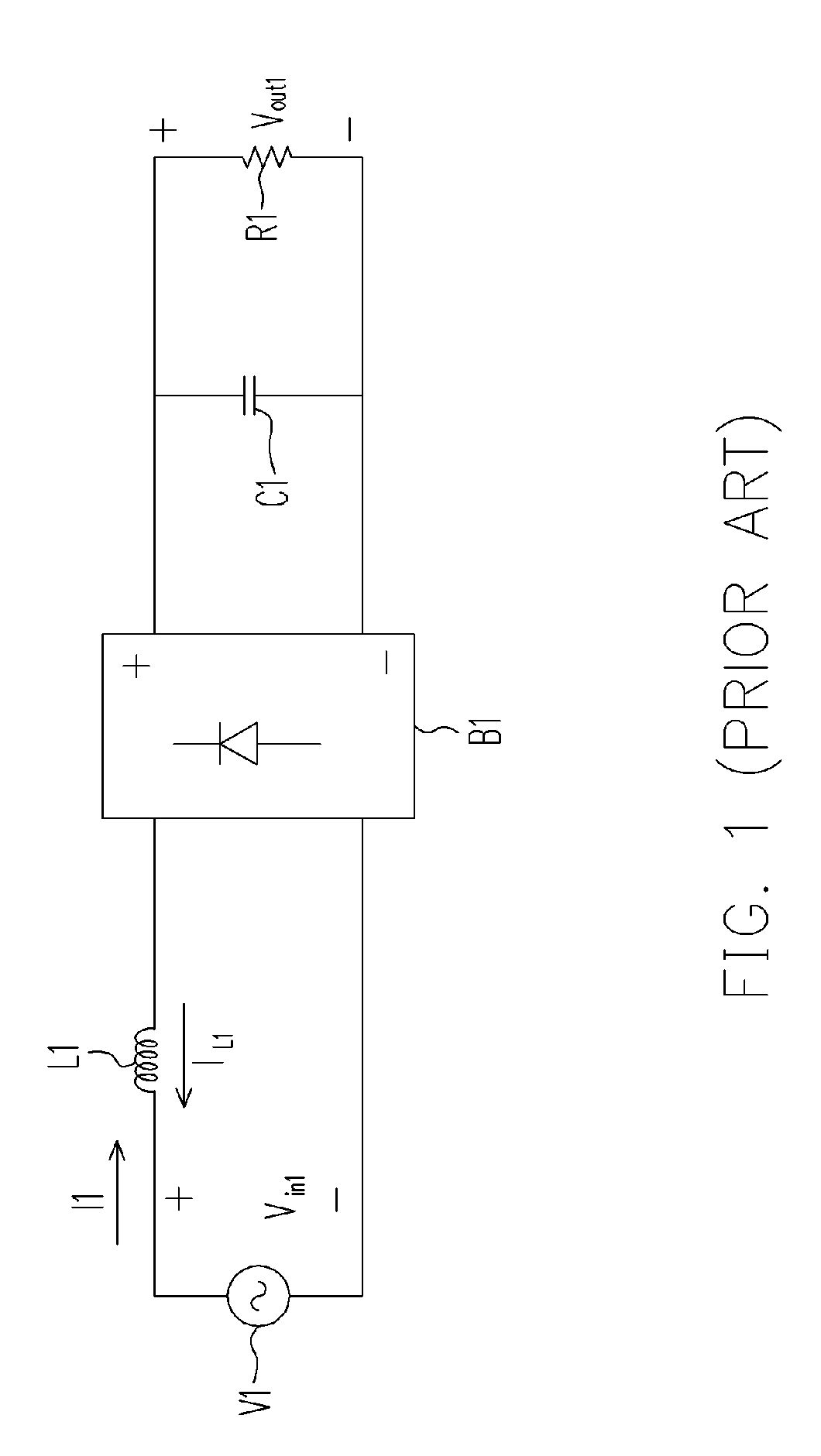
[0026]FIG. 3 is a schematic circuit drawing of a complete PFC apparatus according to an embodiment of the present invention. Referring to FIG. 3, the passive PFC circuit 300 of this embodiment comprises a DC rectification circuit 301. This circuit has a structure similar to that of the conventional passive PFC circuit, which is composed of a first reactance device, such as an inductor L1, a bridge rectifier B1 and a second reactance device, such as a capacitor C1.

[0027] Wherein, the positive AC output terminal of the AC voltage source V1 is coupled to the ...


PUM


Abstract

A power factor correction (PFC) apparatus is disclosed. The apparatus comprises a DC rectification circuit and a PFC auxiliary circuit. In this apparatus, the PFC auxiliary circuit is coupled between the input and output terminals of the DC rectification circuit. According, not only can the conduction time be increased, but the working current peak is restrained. Thus, the increased size of the choke and inductance of the inductor can be prevented.

Description

CROSS-REFERENCE TO RELATED APPLICATION [0001] This application claims the priority benefit of Taiwan application serial no. 94105353, filed on Feb. 23, 2005. All disclosure of the Taiwan application is incorporated herein by reference. BACKGROUND OF THE INVENTION [0002] 1. Field of the Invention [0003] The present invention relates to a power factor correction (PFC) apparatus, and more particularly to a passive PFC apparatus for improving power factors. [0004] 2. Description of the Related Art [0005] Power factor reflects the relation between effective power and apparent power consumption of electricity. It is defined as the ratio of the effective power to the apparent power (VA, or voltage multplying current). Basically, a power factor can be used to measure the efficiency of electricity usage. The higher the power factor, the lower the AC source current, and thus the better the electricity usage efficiency. The circuit operational principle of a power factor correction (PFC) circu...

Claims


Application Information

Patent Timeline
IPC IPC(8): H02M7/06
CPCH02M1/4208Y02B70/126Y02B70/10Y02P80/10
Inventor TANG, ALLEN PAK CHUEN
Owner NEWTON POWER
Why Eureka
Try Eureka