Performing OPC on structures with virtual edges

a virtual edge and opc technology, applied in the field of photolithographic processing, can solve the problems of previously impossible to correct for expected errors, and achieve the effect of improving the edge position error (epe) of a feature and enhancing the fidelity of objects

Active Publication Date: 2006-08-24
SIEMENS PROD LIFECYCLE MANAGEMENT SOFTWARE INC
View PDF27 Cites 38 Cited by
  • Summary
  • Abstract
  • Description
  • Claims
  • Application Information

AI Technical Summary

Benefits of technology

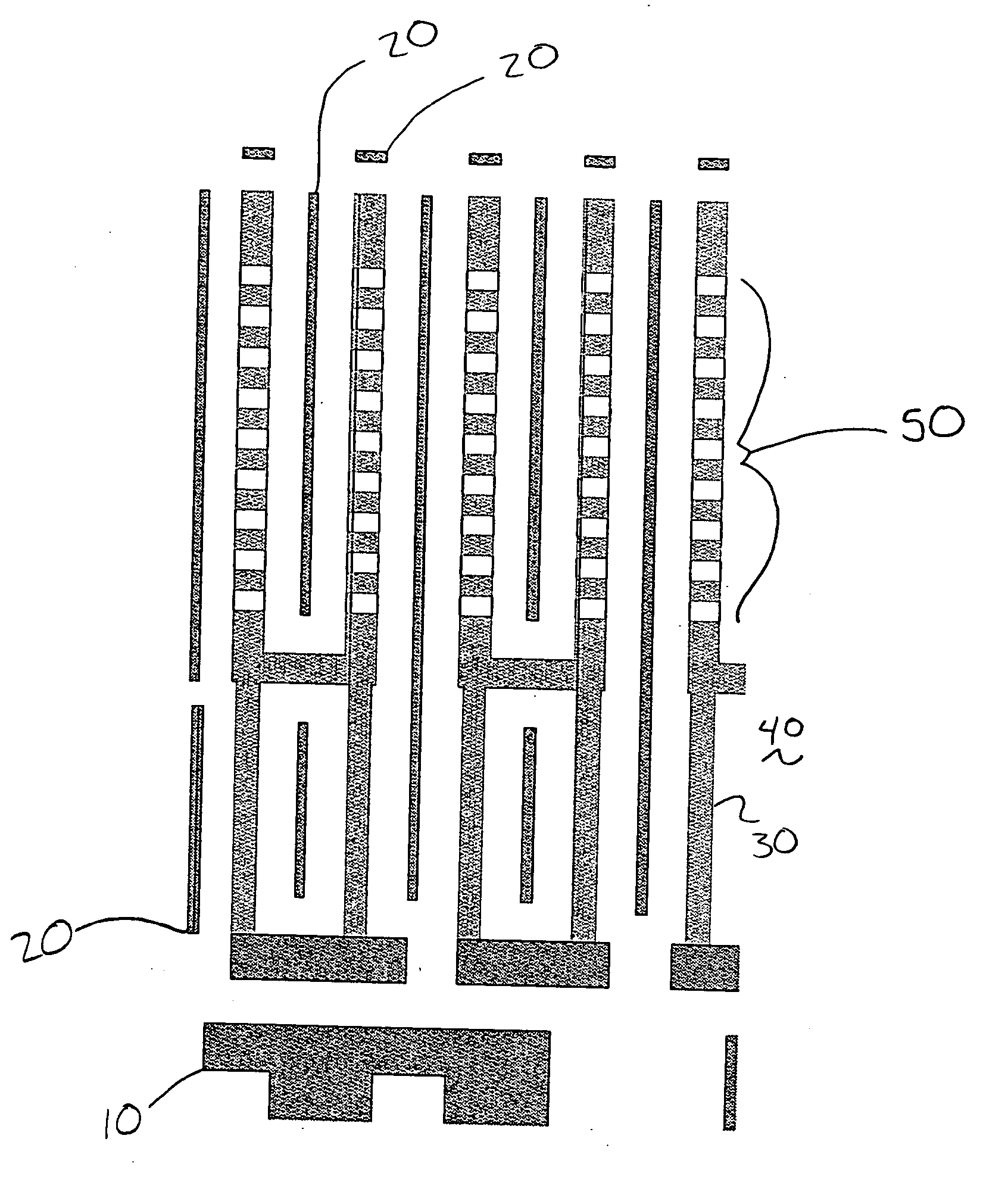
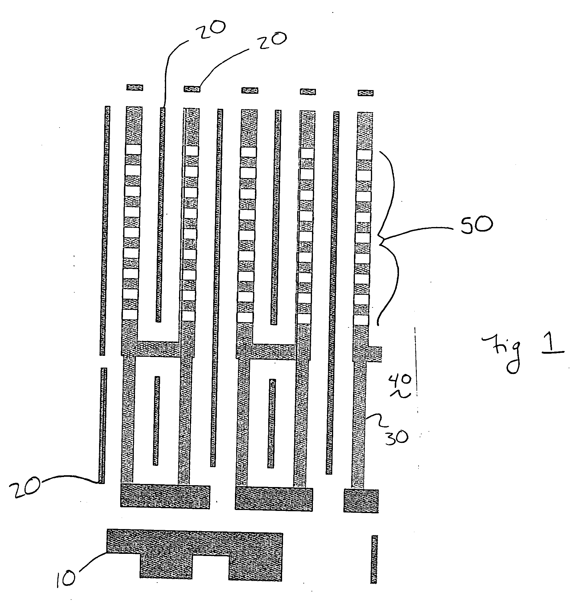
[0006] To solve the problems described above, the present invention is a method for enhancing the fidelity of objects to be printed using phase-shifters on a photolithographic mask or reticle. Features to be created on a photolithographic wafer are formed with phase-shifting regions having edge segments that are positioned adjacent to non-phase-shifting regions that have virtual edges. In order to improve the edge position error (EPE) of a feature in an area that corresponds to a virtual edge, OPC is performed on one or more edges of the adjacent phase-shifting regions. In one embodiment, the amount by which an edge of a phase-shifting region is moved is determined based on the EPE at a virtual edge and an adjacent edge segment of a phase-shifting region.

Problems solved by technology

If an expected edge position error (EPE) is found in a region that does not have a corresponding edge that can be adjusted, it has been previously impossible to correct for the expected error.

Method used


Image

  • Performing OPC on structures with virtual edges
  • Performing OPC on structures with virtual edges
  • Performing OPC on structures with virtual edges

Examples


Embodiment Construction

[0014] As indicated above, the present invention is a technique for improving the edge position error of a feature printed on a wafer in a region that corresponds to a virtual edge of a phase-shifter on a mask or reticle.

[0015]FIG. 3A is a greatly enlarged illustration of a phase grating structure that comprises a number of phase-shifting regions 80a, 80b, 80c, that are surrounded by and alternate with a non-phase-shifting region 90. Each of the phase-shifting regions 80a, 80b, 80c, is divided into a number of edge segments that are defined by fragmentation endpoints 84. In the example shown, the vertical edges of the phase-shifting regions 80a, 80b, 80c are divided into two edge segments by using three fragmentation endpoints 84 that are positioned at the corners of the phase-shifting regions and at the center of the vertical edges. The horizontal edges of the phase-shifting regions 80a, 80b, 80c are defined as a single edge segment. However, the horizontal edges could be divided ...


PUM

PropertyMeasurementUnit
phase-shiftingaaaaaaaaaa
areaaaaaaaaaaa
sizeaaaaaaaaaa

Abstract

A method for compensating for optical distortions occurring in regions associated with non-phase-shifting regions in a mask or reticle. OPC or other resolution enhancement techniques are performed on one or more edge segments associated with adjacent phase-shifting regions in order to compensate for edge position errors occurring in areas corresponding to non-phase-shifting regions.

Description

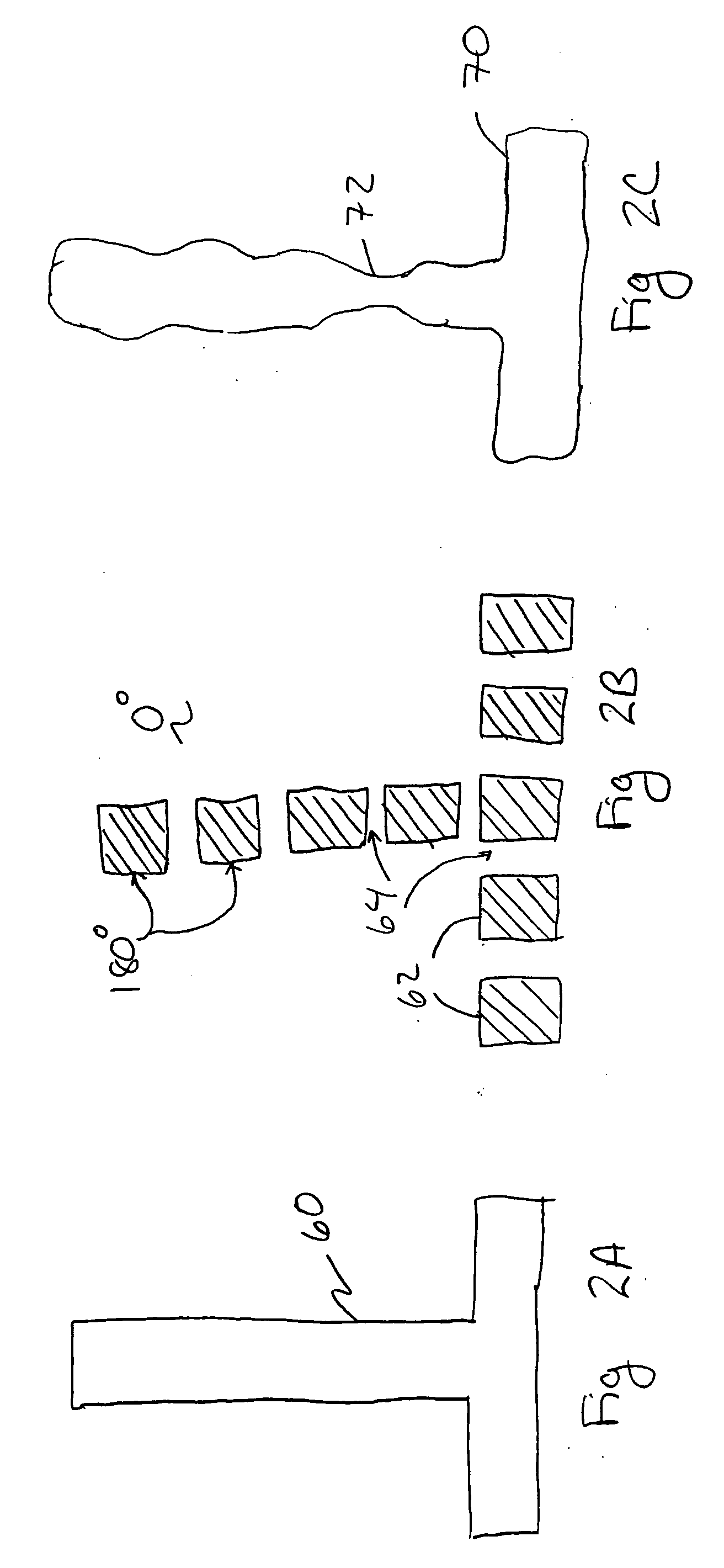
FIELD OF THE INVENTION [0001] The present invention relates to photolithographic processing and in particular to performing optical and process correction (OPC) on structures to be created with phase-shifters. BACKGROUND OF THE INVENTION [0002] In an effort to create an ever increasing number of features on an integrated circuit, many circuit designers are employing a variety of techniques to decrease the size of a feature that can be created with a photolithographic process on a wafer. One technique commonly used to create small features on a wafer is to use phase-shifters instead of opaque feature patterns on a photolithographic mask or reticle. With a phase-shifter, light is shifted 180° out of phase with respect to the phase of light passing through an adjacent non-phase-shifting portion of the mask or reticle. The interfering non-phase shifted and phase-shifted light produces a dark region of very high contrast with the surrounding bright background, enabling the selective patt...

Claims


Application Information

Patent Timeline
Patent Type & Authority Applications(United States)
IPC IPC(8): G03F1/00G03C5/00
CPCG03F1/144G03F1/26G03F1/30G03F1/36
Inventor WORD, JAMES
Owner SIEMENS PROD LIFECYCLE MANAGEMENT SOFTWARE INC
Why Eureka
Try Eureka