Method and apparatus for reducing intraocular pressure

a technology of intraocular pressure and apparatus, applied in the field of medical technology, can solve the problems of aqueous humor not draining properly, excessive intraocular pressure is a major risk factor for glaucoma, and the loss of vision is gradual, so as to prevent infection

Active Publication Date: 2006-08-24
CAMRAS VISION +1
View PDF22 Cites 65 Cited by
  • Summary
  • Abstract
  • Description
  • Claims
  • Application Information

AI Technical Summary

Benefits of technology

[0013] It is still another object of the present invention to provide for a method to replace a filter or ...

Problems solved by technology

While glaucoma is a medical condition which can be caused by several factors, excessive intraocular pressure is a major risk factor for developing glaucoma.
Over time, excessive intraocular pressure can cause damage to the optic nerve resulting in gradual loss of vision and, in some cases, blindness.
Increased intraocular pressure results when aqueous humor cannot drain properly or at an appropriate rate through the trabecular meshwork or other outflow pathways.
However, as with any medication, patients experience different levels of response to the medication, and the side effects of some medications can become intolerable in certain individuals.
Unfortunately, the failure rate of filtration procedures is unacceptably high.
In addition, postoperative intraocular pressure is almost always unstable and unpredictable.
Initial overdrainage can lead to abnormally low intraocular pressure, known as hypotony, which can cause the eyeball to malfunction and delay the patient's postoperative recovery.
Also, scarring or excessive resistance may occur in the subconjunctival, episcleral, or scleral regions (i.e. the sclerostomy site or surgical opening into the anterior chamber), thereby restricting the drainage.
However, this p...

Method used


Image

  • Method and apparatus for reducing intraocular pressure
  • Method and apparatus for reducing intraocular pressure
  • Method and apparatus for reducing intraocular pressure

Examples


Embodiment Construction

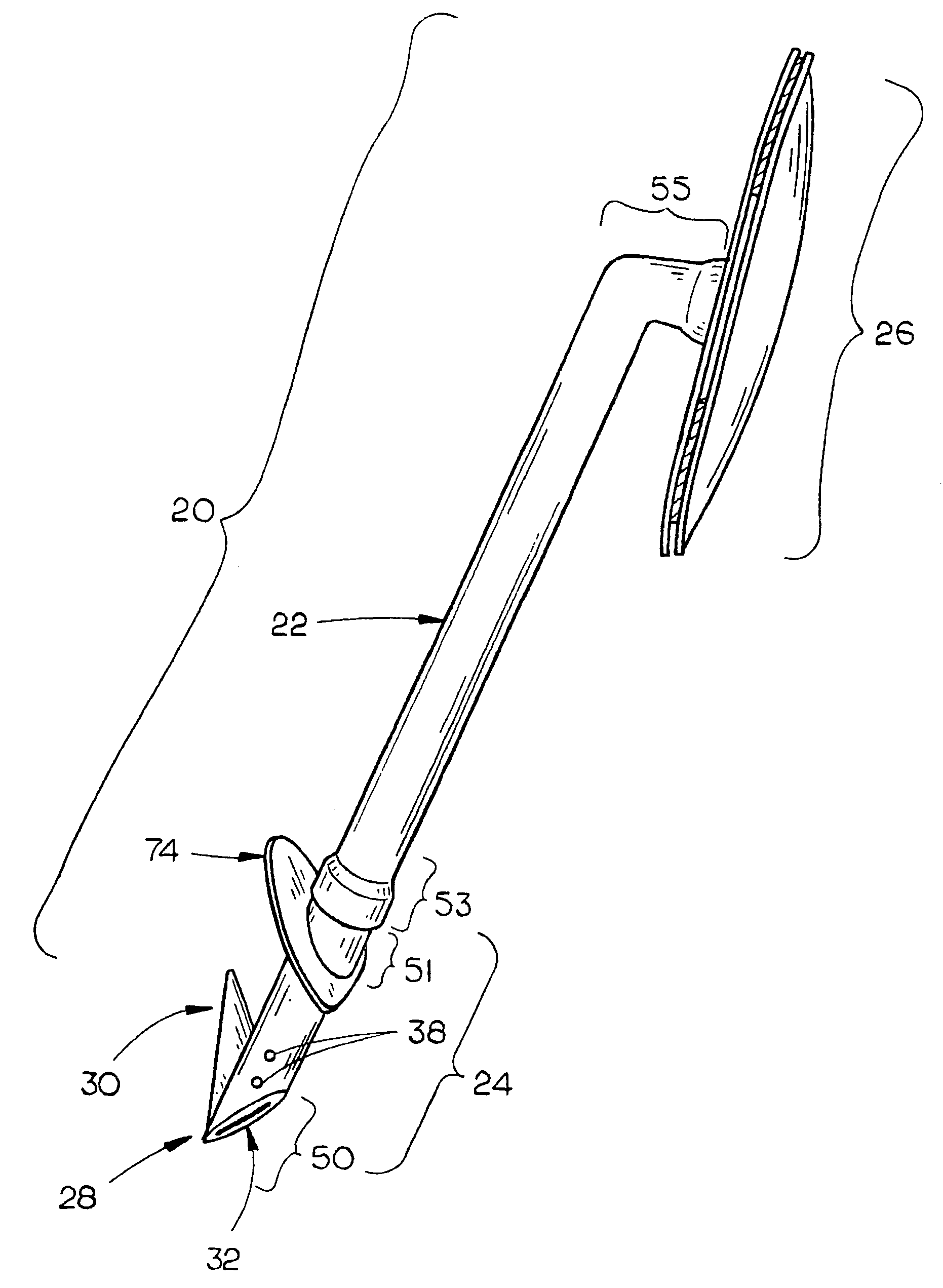
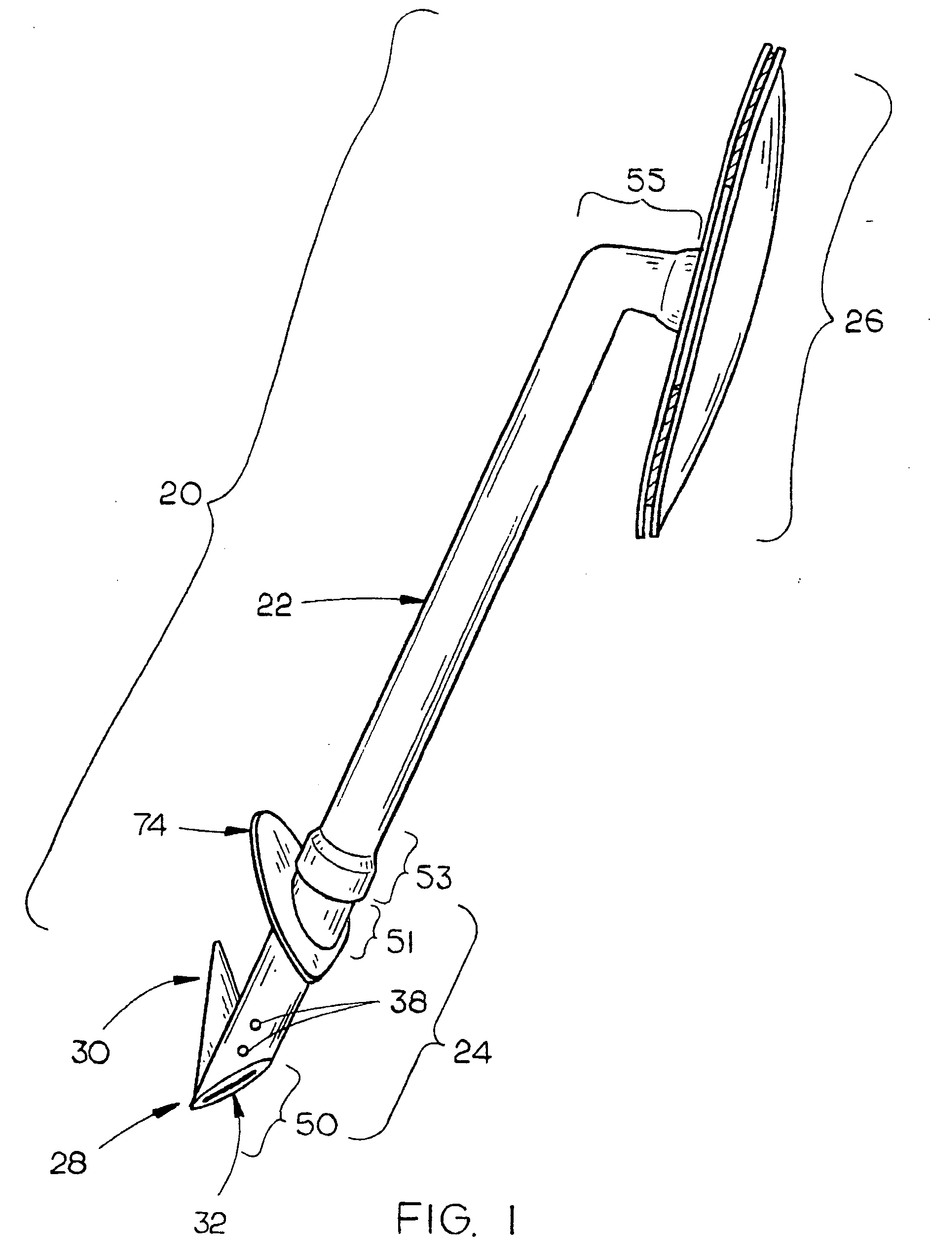
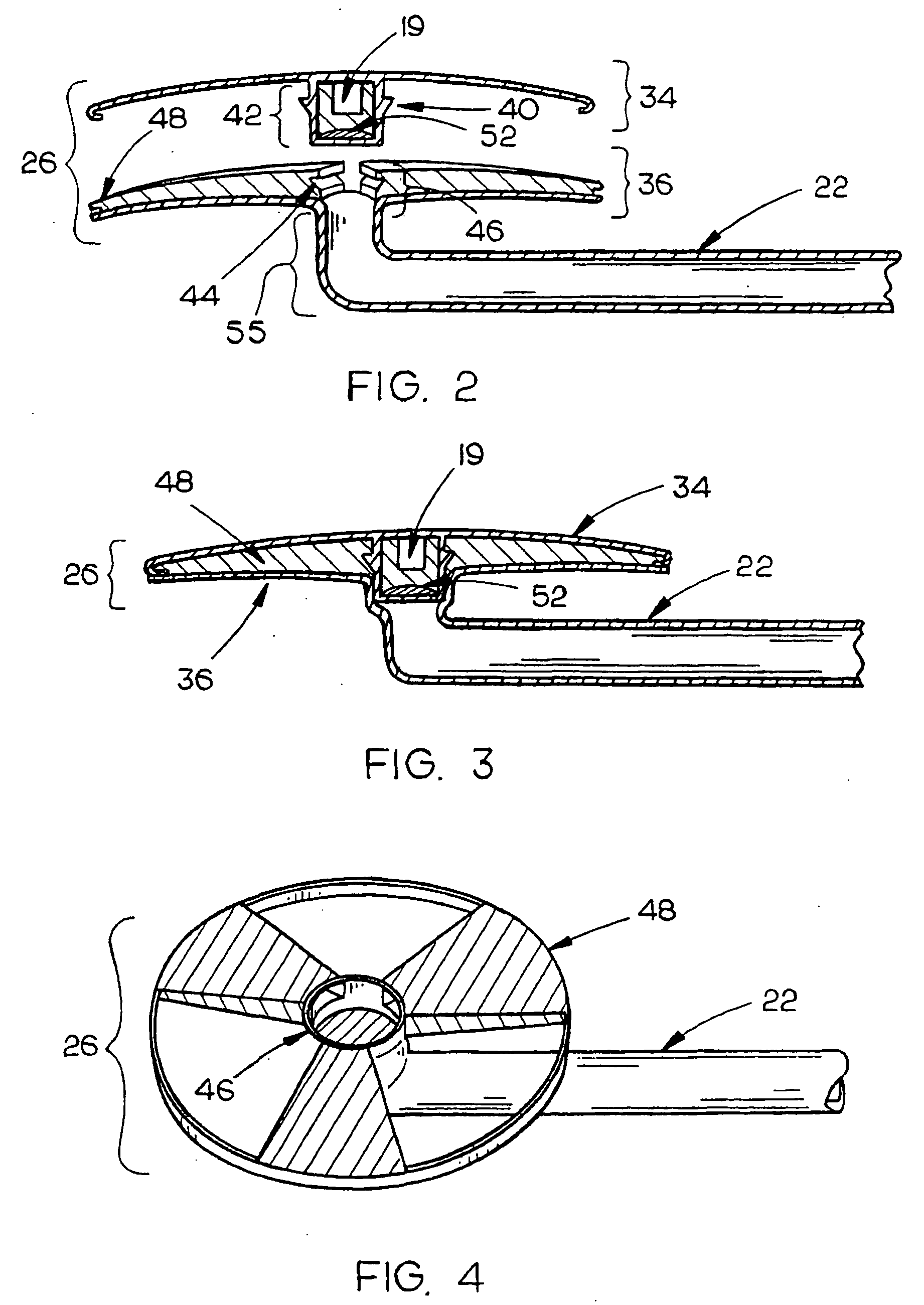
[0032] The present invention provides for a method and apparatus to direct aqueous humor from the anterior chamber of an eyeball to the external surface of the eyeball as a means to predictably regulate intraocular pressure and treat glaucoma. An embodiment of a drainage apparatus 20 according to the present invention is illustrated in FIG. 1. As shown in FIG. 1, the drainage apparatus 20 comprises an inlet assembly 24 having a first end 50 and a second end 51, a tube 22 capable of conducting aqueous humor having a first end 53 and a second end 55, and an outlet assembly 26.

[0033] The inlet assembly 24 is further comprised of a beveled tip 28 formed at the first end 50 of the inlet assembly 24, and an insertion plate 74 formed near the second end 51 of the inlet assembly 24. An opening 32 is formed through the inlet assembly 24 allowing aqueous humor to flow through the inner lumen of the inlet assembly 24. An anchor 30 may also be formed near the first end 50 of the inlet assembly...


PUM


Abstract

An intraocular drainage apparatus for treatment of glaucoma, a device to be used in the insertion of the drainage apparatus, and a method of controllably regulating intraocular pressure in glaucoma patients through the use of the drainage apparatus is described herein. The drainage apparatus is comprised of a tube capable of conducting fluid disposed between an inlet assembly, where aqueous humor enters the apparatus, and an outlet assembly, where aqueous humor exits the apparatus. The inlet assembly is comprised of a beveled tip and preferably an anchor. The beveled tip allows the drainage apparatus to be more easily inserted into an eyeball and the anchor, when employed, functions to hold the beveled tip of the inlet assembly within the anterior chamber of the eyeball. An opening in the beveled tip of the inlet assembly allows aqueous humor from the anterior chamber of the eyeball to flow through the inlet assembly, through the tube to ultimately drain through the outlet assembly, situated on the external surface of the eyeball, so as to be drained out of the eyeball onto the exterior surface of the eyeball. The inserting apparatus is comprised of an insertion prong attached to a first handle. The insertion prong has a sharp, beveled insertion point. The insertion prong also defines an aperture wherein a second prong is slideably received. The drainage apparatus is seated in the inserting apparatus and is positioned at a proper point in the eyeball. The inserting apparatus is then manipulated so that the second prong drives the drainage apparatus into the proper position within the eyeball. The drainage apparatus also provides for the use of micropore filters and/or valves to prevent infection and/or to predictably regulate the flow of aqueous humor from the anterior chamber of the eyeball to the surface of the eyeball, thereby allowing for post-surgical adjustment of the intraocular pressure within the eyeball. An apparatus for removing and replacing these filters and/or valves is also disclosed, as are alternative embodiments of the drainage apparatus and inserting apparatus.

Description

TECHNICAL FIELD [0001] The present invention relates to the field of medical technology, particularly to an apparatus to be implanted in an eyeball for the treatment of glaucoma. BACKGROUND OF THE INVENTION [0002] Glaucoma is one of the leading causes of blindness in the United States. It is estimated that two to three million people in the United States have some degree of visual loss resulting from glaucoma. While glaucoma is a medical condition which can be caused by several factors, excessive intraocular pressure is a major risk factor for developing glaucoma. Over time, excessive intraocular pressure can cause damage to the optic nerve resulting in gradual loss of vision and, in some cases, blindness. Excessive intraocular pressure is caused by an increase in the resistance to outflow of fluid, called aqueous humor, in the anterior chamber of the eyeball, which can be caused by a number of different factors including injury, the aging process, reaction to medication (such as co...

Claims


Application Information

Patent Timeline
IPC IPC(8): A61M5/00
CPCA61F9/00781
Inventor CAMRAS, CARL B.CAMRAS, LUCINDA J.
Owner CAMRAS VISION
Why Eureka
Try Eureka