
Internal adaptor for hip acetabular cage

a technology of acetabular cage and adaptor, which is applied in the field of orthopaedics, can solve the problems that the support ring must be used in all applications, and achieve the effects of reducing cross-section, increasing engagement, and prolonging length

Inactive Publication Date: 2006-08-24
HOWMEDICA OSTEONICS CORP
View PDF68 Cites 34 Cited by
  • Summary
  • Abstract
  • Description
  • Claims
  • Application Information

AI Technical Summary

Benefits of technology

[0013] Further, the present invention provides a cage or shell member and adaptor for use in an acetabular cup assembly having an internal polymeric or ceramic bearing member for securement within the adaptor. The internal polymeric or ceramic bearing member is selected from a plurality of bearing members having different characteristics such as bearing surface size for different heads or inclinations. The adaptor member includes an internal wall of its cavity with a coupling element matching on the external wall of the bearing member. A tapered coupling element may be on the adaptor inner surface and would be compatible with the external tapered securing characteristics of the plurality of bearing members such as ceramic bearings. Optionally, a second additional bearing coupling element may be provided within the cavity of the adaptor, the second securing element being compatible with the securing characteristics of other internal bearing members so that a, for example, polymeric bearing element may be introduced directly into the adaptor. The first coupling element and the second optional coupling element being juxtaposed with one another and placed at relative locations such that the effectiveness of each of the first and second securing elements is maintained in the presence of the other of the first and second securing elements, whereby the one and the another of the internal bearing members each is selectable for effective securement within the adaptor member which in turn is selectable for implantation into the outer cage or shell to complete the acetabular cup assembly.
[0017] The deformable wing, flange or strap is deformable at least in a direction perpendicular to the radial direction and may be oriented at various angles around and extend various lengths with respect to the body of the adaptor. Obviously, the longer the length, the greater the engagement with various areas of the pelvis are possible. The wing, strap or flange may include a reduced cross-section to facilitate deformation or may be made of a ductile material. Alternately, the flange can have a groove or series of grooves to facilitate bending.

Problems solved by technology

This construction has a disadvantage that the support ring must be used in all applications since it receives the outer shell of the acetabular prosthesis.

Method used


Image

  • Internal adaptor for hip acetabular cage
  • Internal adaptor for hip acetabular cage
  • Internal adaptor for hip acetabular cage

Examples


Embodiment Construction

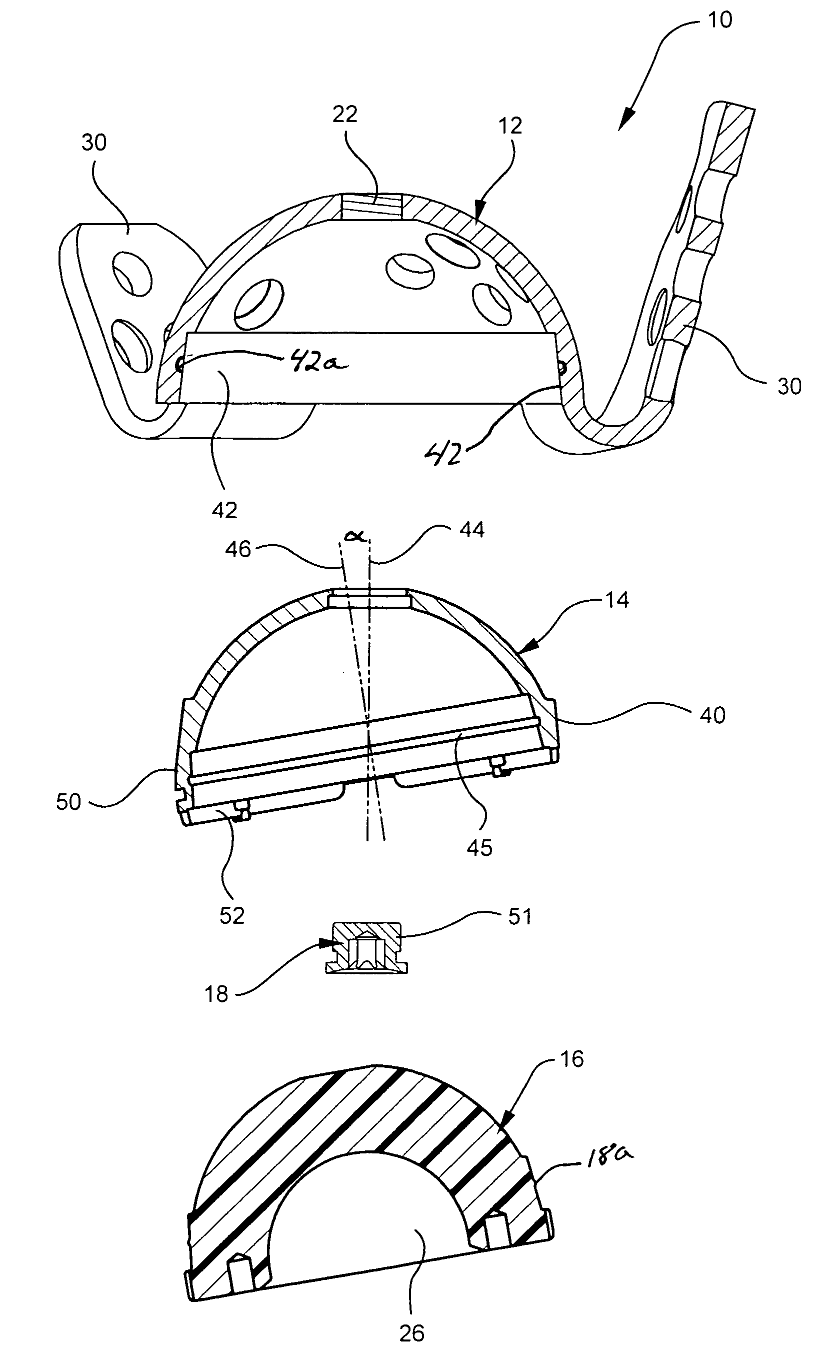
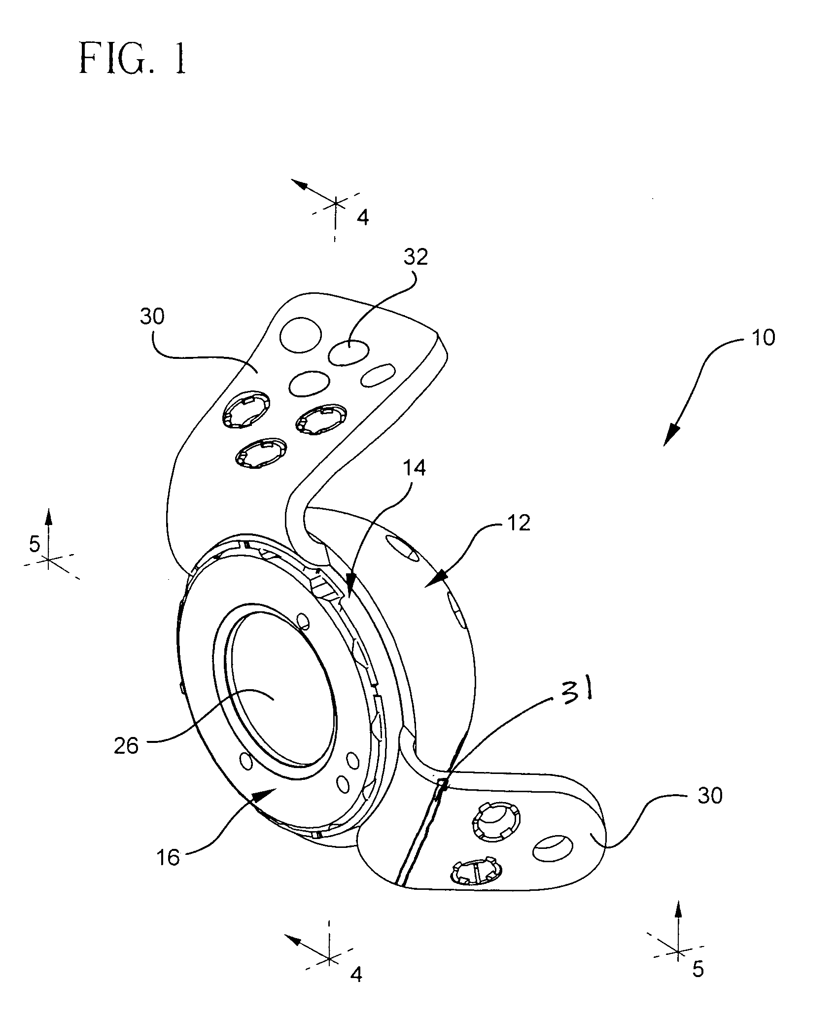
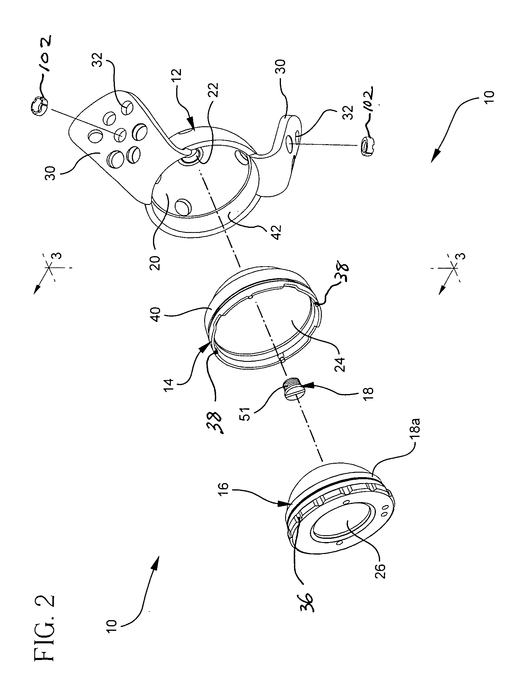
[0029] Referring to FIGS. 1 and 2 there is shown an assembled and an exploded isometric view of the preferred acetabular prosthesis of the present invention generally denoted as 10. Assembly 10 consists of an outer shell or cage 12, an adaptor 14, a bearing insert 16 which, as shown in FIG. 2 is made of polyethylene, and a fastening mechanism 18 such as a screw. Adaptor 14 is designed to be inserted within a cavity 20 of shell 12. Connecting element or screw 18 is adapted to be threaded into the polar hole 22 of the shell 20 to thereby clamp the adaptor in position. The polymeric bearing insert 16 is then inserted into the inner cavity 24 of adaptor 14 and locked therein by any convenient known method. The assembled acetabular cup implant 10 of FIG. 2 is shown in FIG. 1. Bearing insert 16 in turn has an internal cavity 26 for receiving the ball shaped head of a femoral component (not shown). Preferably the adaptor outer surface and shell inner surface have complimentary locking tape...


PUM


Abstract

An acetabular cup assembly for a prosthetic hip joint includes an outer shell for attachment to the acetabulum. The outer shell has an inner surface receiving an adaptor. Complimentary coupling features are provided on the inner surface of the outer shell and the outer surface of the adaptor for coupling the bearing insert to the outer shell. A plurality of adaptors are provided having inclined outer surfaces for engaging an inner surface of the outer shell and having an inner surface for receiving the bearing insert. Each shell has at least one radial extending strap or flange for engaging the bone surrounding the acetabulum. The straps or flanges may be of different sizes and shapes and may be at different locations on the shell. The inner surface of the adaptor includes coupling features be able to receive different design bearing inserts.

Description

BACKGROUND OF THE INVENTION [0001] This invention relates generally to orthopedics and, in particular, to a versatile reconstruction system associated with an acetabular prosthetic implant. [0002] The replacement of members of a natural hip joint (femoral and acetabular) with prosthetic implants has become widespread and is being accomplished with ever-increasing frequency. The variety of conditions encountered when effecting such implants has led to the use of various bearing materials and attachment methods placed at an optimum position and orientation, as determined by conditions encountered at the site of the implant. The choice of a particular material for the bearing, as well as the size, positioning and orientation of the bearing member, is determined by the surgeon performing the procedure. Usually such choices are made on the basis of a pre-operative assessment of the needs of a particular patient; however, at times the choices are not completed until the implant site actua...

Claims


Application Information

Patent Timeline
IPC IPC(8): A61F2/34
CPCA61B17/86A61F2/34A61F2002/30332A61F2002/30367A61F2002/30403A61F2002/30433A61F2002/30487A61F2002/30507A61F2002/30578A61F2002/30616A61F2002/30785A61F2002/30787A61F2002/30794A61F2002/30808A61F2002/3082A61F2002/3233A61F2002/3401A61F2002/3404A61F2002/3411A61F2002/3443A61F2002/3448A61F2002/3451A61F2002/3482A61F2220/0025A61F2220/0033A61F2220/0041A61F2310/00179A61F2002/3054A61F2002/305A61F2002/3403A61F2002/3079
Inventor MONTOYA, JORGE A.WATT, PHILIP MORGAN
Owner HOWMEDICA OSTEONICS CORP
Learn More