Optimization by using output drivers for discrete input interface

a technology of output drivers and input interfaces, applied in the field of output drivers, can solve the problems of not utilizing all the installed output functions, adding cost to the design of the microprocessor controller, and insufficient microprocessor ports to meet all the input/output port requirements, etc., to achieve the effect of reducing cost, reducing hardware proliferation, and saving microprocessor ports

Active Publication Date: 2006-08-24
DELPHI TECH IP LTD
View PDF5 Cites 8 Cited by
  • Summary
  • Abstract
  • Description
  • Claims
  • Application Information

AI Technical Summary

Benefits of technology

[0005] An advantage of the present invention is the elimination of hardware proliferation, thereby leading to decreased cost.
[0006] Another advantage of the present invention is the utilization of a serial peripheral interface to interface the discrete input, thereby saving microprocessor ports without compromising design performance.
[0007] In one form thereof, the present invention provides a method for design optimization of an engine control module to eliminate hardware proliferation using a design having outputs with fault detection circuitry, including the steps of: identifying a spare output of an output driver; associating a serial peripheral interface and a desired input with the spare output; and enabling the process to access the fault detection capability of the spare output through the serial peripheral interface to determine an input value.
[0008] In another form thereof, the present invention provides a method for design optimization of a processor to eliminat

Problems solved by technology

Occasionally, the microprocessor ports are not sufficient to meet all the input/output port requirements.
The second option entails using the next higher end microprocessor that can accommodate all the required functions, thereby adding cost to the design of the microprocessor controller.
Most designs do not uti

Method used


Image

  • Optimization by using output drivers for discrete input interface
  • Optimization by using output drivers for discrete input interface
  • Optimization by using output drivers for discrete input interface

Examples


Embodiment Construction

[0023] The embodiments discussed below are not intended to be exhaustive or limit the invention to the precise forms disclosed in the following detailed description. Rather, the embodiments are chosen and described so that others skilled in the art may utilize their teachings.

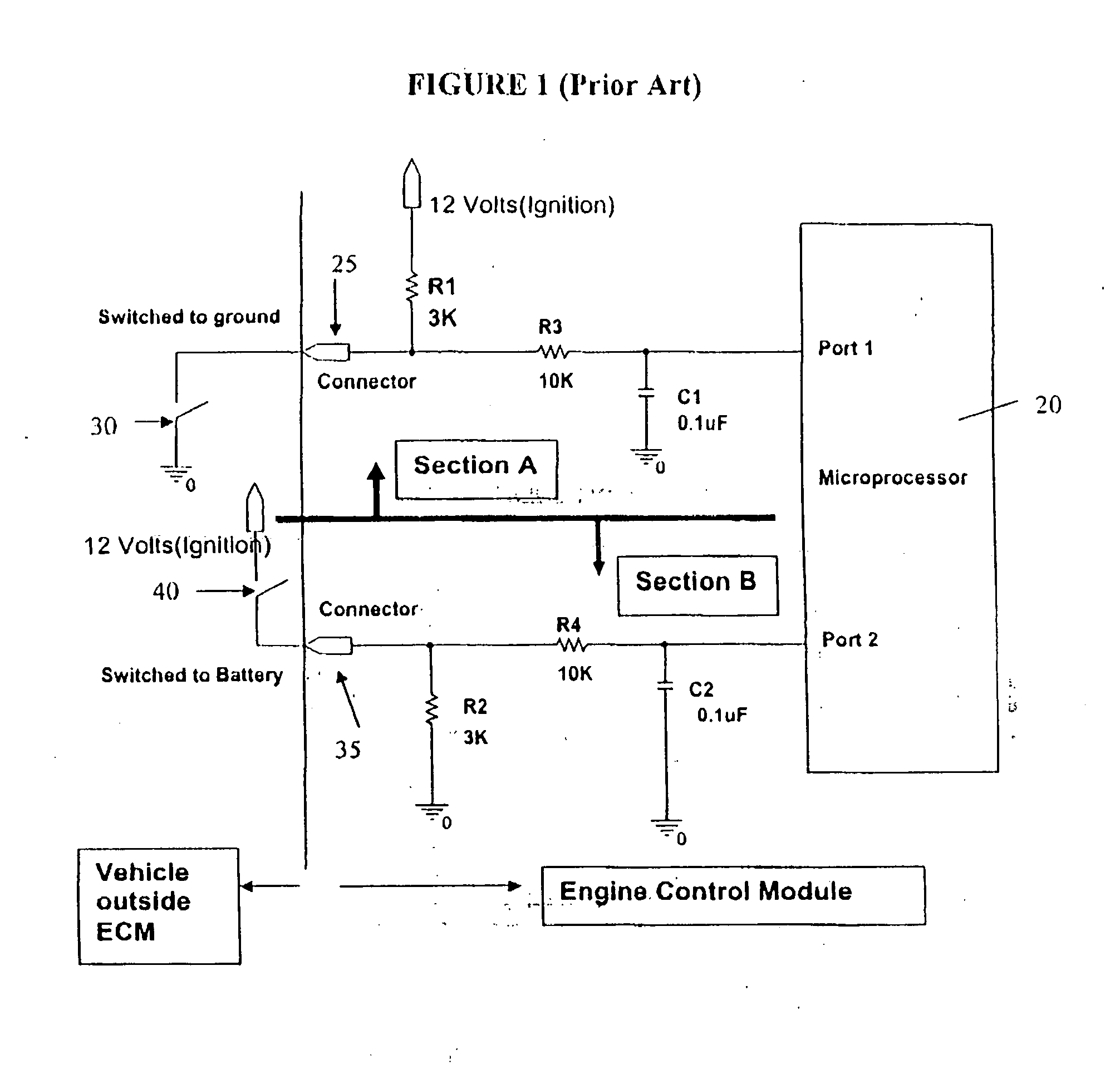
[0024] Referring now to FIG. 1, a conventional discrete interface is shown. Ports 1 and 2 of microprocessor 20 are discrete input ports. Section A of FIG. 1 shows the typical interface for a switched to ground type interface. Port 1 of the switched to ground type interface reads “0” if switch 30 is closed and “1” if switch 30 is open. Resistor R3 and capacitor C1 in Section A are used for signal filtering. Connector 25 connects the circuitry shown in Section A to the remainder of the vehicle circuitry outside the engine control module, i.e., switch 30. Section B of FIG. 1 shows the typical interface for a switched to battery type interface. Port 2 of the switched to battery type interface reads “0” if switch 4...


PUM


Abstract

The invention relates to design optimization of microprocessors using spare driver outputs for discrete input interfaces. An output driver or pre-FET driver is used to interface a discrete input for a microprocessor. To read the discrete interface, a fault detection mechanism of the pre-FET driver or the output driver is used. Monitoring the fault register of the output driver allows the condition of the external switch to be understood. The circuit is able to read either a switched to battery type interface or a switched to ground type interface, thereby eliminating hardware proliferation. The fault register is read through a serial peripheral interface (SPI) bus, thereby removing the need for a dedicated microprocessor pin required for the interface. Toggling the gate in the pre-FET driver interface permits adding diagnostic capability for the discrete input interface.

Description

TECHNICAL BACKGROUND [0001] The present invention relates generally to output drivers used in engine control modules. BACKGROUND OF THE INVENTION [0002] In a conventional microprocessor controller design, the microprocessor resources are allocated for input, output, and control functions. Occasionally, the microprocessor ports are not sufficient to meet all the input / output port requirements. In these cases, two options are available. The first option entails using one port for multiple functions, resulting in multiple software sets and hardware base models. The second option entails using the next higher end microprocessor that can accommodate all the required functions, thereby adding cost to the design of the microprocessor controller. [0003] Current output drivers and pre-FET (Field Effect Transistor) drivers are used only for output interface. Most designs do not utilize all of the installed output functions for a particular base model microprocessor. Thus, the unused outputs b...

Claims


Application Information

Patent Timeline
IPC IPC(8): G06F11/00
CPCG06F13/4072
Inventor NAIR, BALAKRISHNAN
Owner DELPHI TECH IP LTD
Why Eureka
Try Eureka