
Multi-view display

Active Publication Date: 2006-08-31
APTIV TECH LTD
View PDF99 Cites 155 Cited by
  • Summary
  • Abstract
  • Description
  • Claims
  • Application Information

AI Technical Summary

Benefits of technology

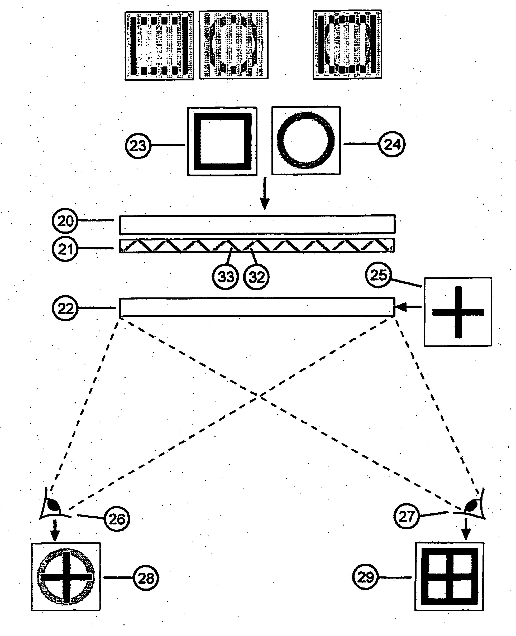
[0024] In the present invention, the unbraiding viewing angle manipulation means has the ability to present images displayed on the display device to different viewing angles. This can be achieved by interlacing two different image directing films each of which is designed to present images to a viewing angles angle which is different to the other interlaced privacy film.
[0037] In this embodiment the combination of a manipulation means preferably an interlaced privacy film or light directing means is used in combination with interlaced specified viewing angle pixels. The combination of these mechanisms allows greater control of the viewing angle to which images are presented.
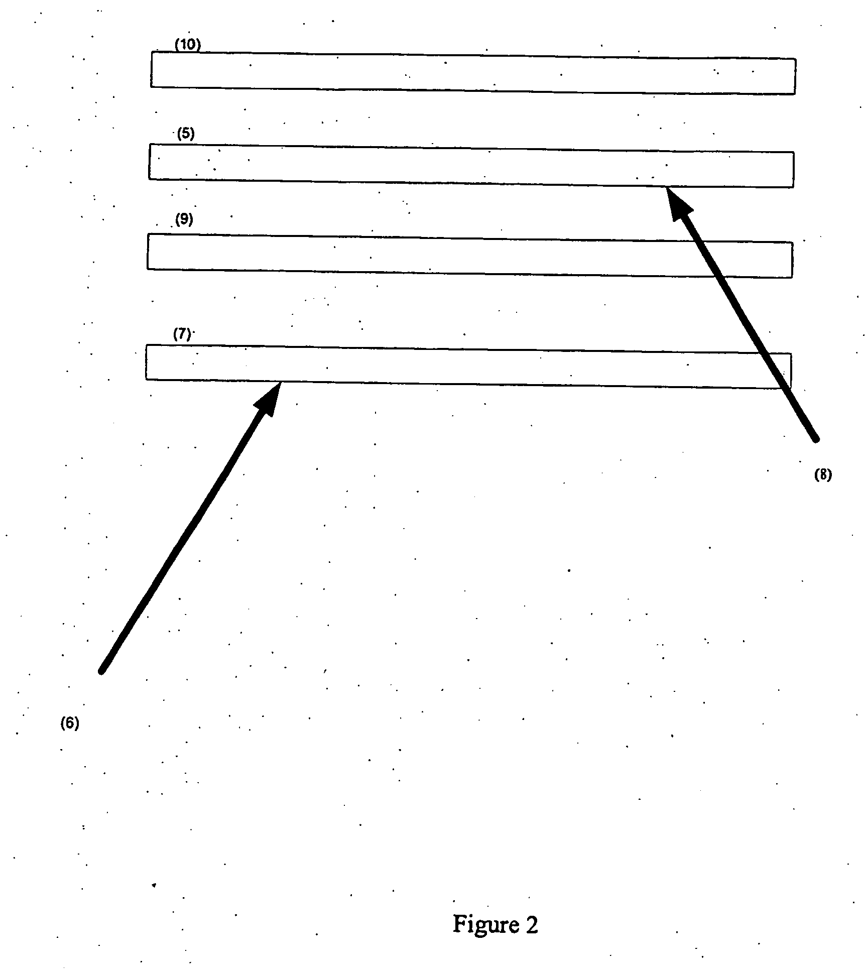
[0044] In the multi-layered setup used in a multi view display as described here-in the display is required to be transparent. Hence in a real life scenario—the multi-layered multi view display is used in a car—if the driver was looking at the rear image layer with a viewing direction of about 60 degrees in the plane perpendicular to the floor and parallel with the horizontal and with the front image layer with an optimal viewing direction of −60 degrees in said plane then the driver will be able to see the image on the rear image layer and not on the from image layer. Conversely, the passenger, sitting to the other side of the display, can see only information from the front image layer. Hence the passenger can view entertainment only and the drive can view navigation only. Thus limited viewing angle, which was previously considered as a disadvantage in the industry, combined with multiple layered displays can be used to multiplex images to multiple viewers which is an unexpected advantage.
[0055] In a preferred embodiment two display layers are overlapped and transparent and are backlit. The front layer has a narrow viewing angle to the left (from the viewer's perspective) behind this is a further narrow viewing angle display but acting upon it is a wide angle diffusion refractor. Hence the images displayed on the rear layer are viewable from a wide viewing angle and the images displayed on the front layer are viewed only from the left (and are viewed as being layered on top of images displayed on the back layer). The diffusing refractor will assist in overcoming the moire interference arising as a result of layering two like substrates.

Problems solved by technology

This is federally mandated safety requirement in many countries and is somewhat of a disadvantage as it is desirable for the front passenger, and only the front passenger, to view in-car entertainment.
In practice many owners disable this safety feature resulting in potentially fatal distraction for the driver.
With present systems this would interrupt the passenger's entertainment.
A potential solution would be to supply separate displays to the passenger and driver, however this is increases expense and takes up almost double the area restricting design flexibility of the dash board control canter and reducing the space available for peripheral devices and storage space.
Long aeroplane flights are particularly boring for passengers.
This problem has been alleviated in some aeroplanes with separate displays for each passenger, however a display for each passenger generally increases expense requires individual displays to be quite small, and can add significant weight to the plane increasing costs for airlines.
It has previously been considered undesirable for displays to have a narrow viewing angle because this prohibits multiple users from viewing the same image.

Method used


Image

  • Multi-view display
  • Multi-view display
  • Multi-view display

Examples


Embodiment Construction

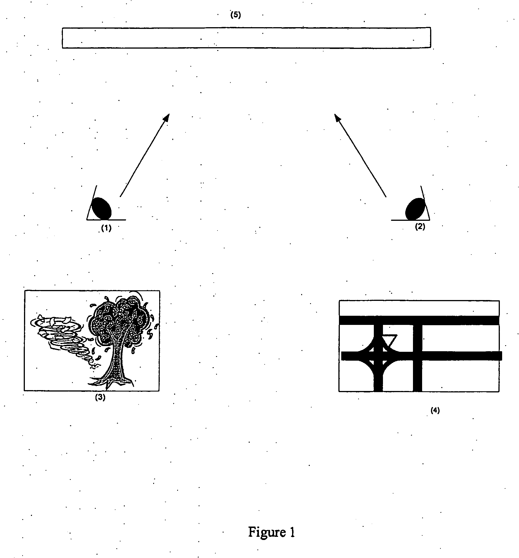
[0077] In a first preferred embodiment a single layer display is used to at least two different images or display contents each image / display-content being presented to a different viewing angle to the images / display-content.

[0078] Figure one illustrates single layer multi view display used as an in-car navigation / entertainment device. A viewer (1) looking at the display (5) in the direction shown sees a movie being played (3), whilst a second viewer (2) looking at the display in the direction shown sees the image of a navigation system (4). In this embodiment the display layer (5) is adapted such that it comprises interlaced pixels of two different viewing angles. The movie is displayed on pixels of one viewing angle and the navigation images are displayed on pixels of the other viewing angle.

[0079] In a further preferred embodiment a multi-layered multi view device is used to display at least two different images or display contents each image / display-content being presented to ...


PUM


Abstract

A multi view display (5) provides different viewing angles for different images (3, 4). The display (5) may comprise a single screen on which two or more images (3, 4) are interleaved, or a number of overlapping screens on which respective images (3, 4) are displayed. Viewing manipulation means such as privacy films or lenticular arrays control the viewing angles for each image (3, 4). The multiview display (5) may be used in a vehicle, to simultaneously display a movie (3) to a passenger (1), and a navigation image (3) to a driver (2).

Description

TECHNICAL FIELD This invention related to the field of electronic information display. BACKGROUND ART [0001] In-car navigation systems and in-car entertainment systems are available as an accessory in new cars, or are available separately for retrofit, commonly called after market sales. The displays for the systems are placed in or on top of the car dash board. Since the displays are typically of the wide-viewing angle colour liquid crystal type, both the front passenger and the driver may see the display. The display may be supplied with information so that it forms part of the car's navigation system or part of the entertainment system at any one time. If an in-car entertainment system is fitted in view of the driver, the video component such as television and DVD must be disabled whilst the car is in motion, so not to distract the driver who is responsible for the safety of the vehicle. This is federally mandated safety requirement in many countries and is somewhat of a disadvan...

Claims


Application Information

Patent Timeline
IPC IPC(8): G09F19/14B60K35/00G02F1/133G02F1/1335G09F19/12
CPCB60K35/00B60K2350/901B60K2350/903G02F1/1323G02F1/133504G09F9/35G09F19/14B60K35/656B60K35/654G02B27/02
Inventor ENGEL, GABRIEL DAMON
Owner APTIV TECH LTD
Learn More