Control system, valve base control equipment and submodule integration method

A valve-based control equipment and control system technology, applied in the direction of DC network circuit devices, electrical components, circuit devices, etc., can solve the problem of not meeting the control and protection requirements of modular flexible DC transmission valves, not having real-time control capabilities of different sub-modules, etc. problem, to achieve the effect of improving data throughput, real-time performance and reliability of data transmission, increasing computing speed, and reducing system control delay

Inactive Publication Date: 2011-07-20
CHINA ELECTRIC POWER RES INST +1
View PDF2 Cites 24 Cited by
  • Summary
  • Abstract
  • Description
  • Claims
  • Application Information

AI Technical Summary

Problems solved by technology

Since the sub-modules include sub-module controllers, IGBTs, protection thyristors and bypass switch components, while traditional DC transmission valve-based electronic equipment is only an actuator, it does not have real-time control capabilities for different sub-modules except for valve monitoring and protection functions. It can no longer meet the control and protection requirements of modular flexible DC transmission valves, so a device with real-time control and protection functions is needed to meet the requirements of modular multi-level flexible DC transmission

Method used


Image

  • Control system, valve base control equipment and submodule integration method
  • Control system, valve base control equipment and submodule integration method
  • Control system, valve base control equipment and submodule integration method

Examples


Embodiment Construction

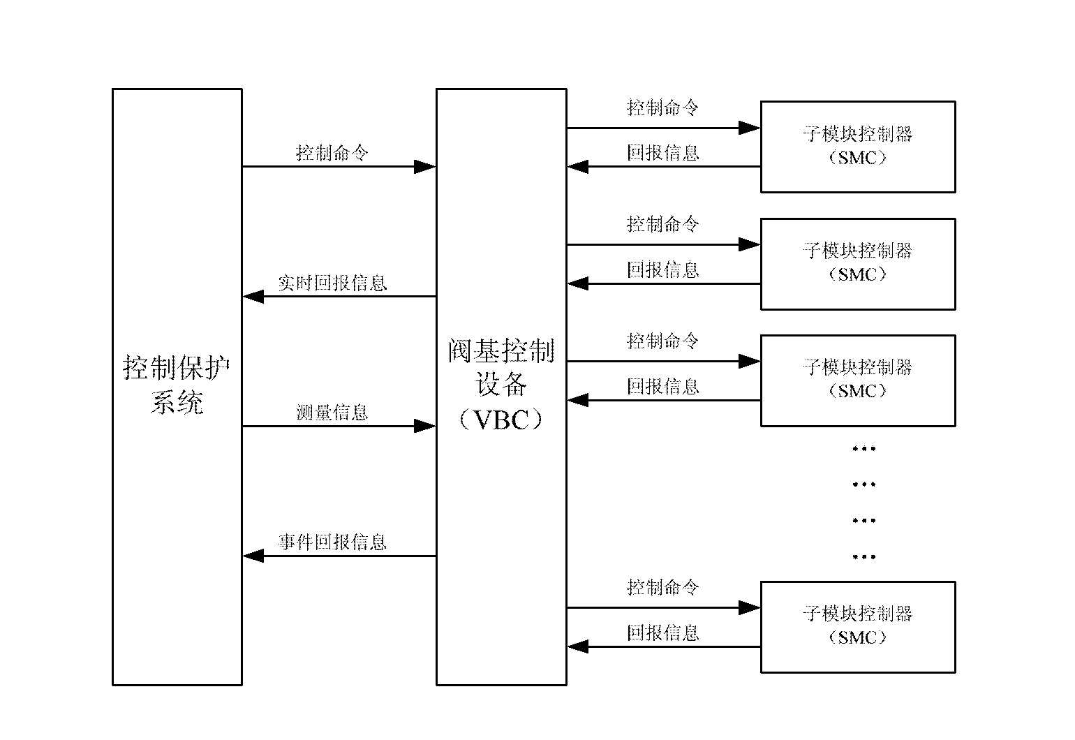
[0023] The valve-based control equipment is the interface equipment of the modular multi-level flexible DC transmission control and protection system and the converter valve, and is mainly used to complete the control, monitoring and protection of the valve. Whenever the control and protection system issues a valve control command, the valve base control device switches or bypasses the converter valve according to the command.

[0024] The specific implementation manners of the present invention will be further described in detail below in conjunction with the accompanying drawings.

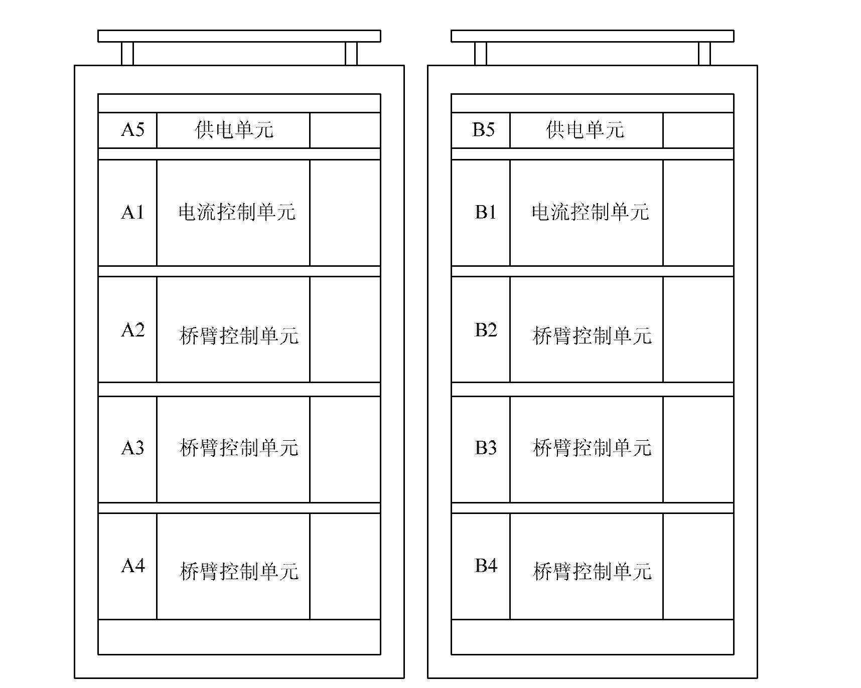
[0025] figure 1 Among them, the valve base control equipment adopts the hardware structure of the current control unit and the bridge arm control unit, and is composed of two panel cabinets. A1 and B1 are two independent current control units, and A2 to A4, B2 to B4 are 6 independent The bridge arm control unit, A5 and B5 are two independent power supply units, and the two current control units ...


PUM


Abstract

The invention provides a control system, valve base control equipment and a submodule integration method. Valve base control equipment consists of two symmetric screen cabinets, wherein each screen cabinet is provided with a power supply unit, a current control unit and a bridge arm control unit; and controllers of the valve base control equipment, a control system and a submodule are connected with one another through optical fibers. All communication interfaces are in a CRC (Cyclic Redundancy Check) check based optical fiber serial communication mode of a reverse Manchester encoding form, so that data throughput is greatly increased, system control time delay is reduced, and real-time control and protection functions of a modularized multi-level flexible direct current valve can be finished. In the method, a hardware structure of the current control unit and the bridge arm control unit is adopted, so that system-level current balance control and valve-level capacitive voltage balance control are clearly divided, and the requirements for modularized multi-level real-time control are met.

Description

Technical field: [0001] The invention relates to the field of power electronic direct current transmission of a power system, in particular to a method for integrating a valve base control device, a control system and a sub-module. Background technique: [0002] The modular multi-level converter is composed of multiple sub-modules connected in series. It is necessary to perform different real-time switching controls on individual sub-modules according to the capacitor voltage and the working status of the sub-modules. The more levels, the shorter the real-time control period, and the capacitor Voltage balance control is more difficult to achieve. Since the sub-modules include sub-module controllers, IGBTs, protection thyristors and bypass switch components, the traditional DC transmission valve-based electronic equipment is only an actuator, and does not have real-time control capabilities for different sub-modules except for valve monitoring and protection functions. It ha...

Claims


Application Information

Patent Timeline
Patent Type & Authority Applications(China)
IPC IPC(8): H02J1/00
Inventor 杨岳峰高阳王韧秋张新刚贺之渊
Owner CHINA ELECTRIC POWER RES INST
Why Eureka
Try Eureka