Control method for electro-magnetic synchronous motor

A technology of synchronous motor and control method, applied in motor generator control, electronic commutation motor control, AC motor control and other directions, can solve the problems of reference current error, power factor drop, no unified solution, etc., to achieve power factor control Accurate, restrained inductance parameter variation, simple and clear control structure

Active Publication Date: 2014-11-12
CSR ZHUZHOU ELECTRIC LOCOMOTIVE RES INST
View PDF3 Cites 0 Cited by
  • Summary
  • Abstract
  • Description
  • Claims
  • Application Information

AI Technical Summary

Problems solved by technology

But this method also has some deficiencies: (1) When the d-axis current is given according to the model calculation, the d-axis ignores the influence of leakage inductance, which will reduce the control accuracy; (2) The motor inductance parameter will change with the current change, according to The reference current calculated by the formula will have errors, resulting in the accuracy of the steady-state power factor after the current closed-loop control cannot be guaranteed
(3) There is no solution given under different power factor requirements
This method also has some shortcomings: (1) The air gap angle δ requires very complicated calculation of flux linkage, and there is no unified solution at present
(2) Affected by motor parameters and measurement errors, it is easy to cause inaccurate estimation of air gap angle and inaccurate orientation
(3) If using ism=0 control, the power factor will decrease with the increase of load current
(4) It cannot meet the user's requirements for arbitrarily controllable power factor
(5) The power factor cannot be precisely controlled

Method used


Image

  • Control method for electro-magnetic synchronous motor
  • Control method for electro-magnetic synchronous motor
  • Control method for electro-magnetic synchronous motor

Examples


Embodiment Construction

[0043] The present invention will be further described in detail below in conjunction with the accompanying drawings and specific embodiments.

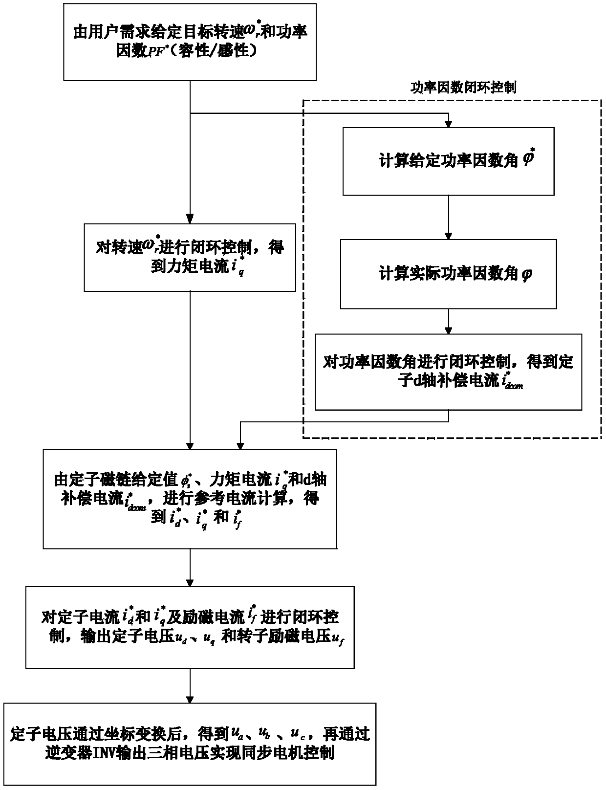
[0044] Such as image 3 and Figure 4 Shown, the control method of electric excitation synchronous motor of the present invention, flow process is:

[0045] (1) The target speed is given by the user's demand and power factor PF * (capacitive / inductive); where, is the given speed, ω r is the rotational speed of the synchronous motor SM measured by the sensor; PF * (capacitive / inductive) is given for the power factor required by the user.

[0046] (2) Through the PI regulator to the target speed Carry out closed-loop control to obtain the stator torque current (that is, the q-axis current given value ); Calculate the given power factor angle Actual Power Factor Angle And perform closed-loop control on the power factor angle to obtain the stator d-axis compensation current

[0047] Power factor is generally divided i...


PUM


Abstract

A control method for an electro-magnetic synchronous motor comprises the steps that firstly, the target revolving speed and a PF* are set according to the user demand; secondly, closed-loop control is carried out on the target revolving speed to obtain a stator moment current, a set power factor angle and an actual power factor angle are calculated, and closed-loop control is carried out on the factor angles to obtain a stator d-axis offset current; thirdly, a current and stator magnetic linkage set value and a stator d-axis current compensation quantity are set through a stator q-axis to calculate a stator d-axis current set value and a magnet winding current set value; fourthly, closed-loop control is carried out on a stator d-axis current set value, a stator q-axis current set value and the magnet winding current set value, and the set stator voltage ud, the set stator voltage uq and the rotor excitation pressure uf are output; fifthly, the voltage ua, the stator voltage ub and the stator voltage uc of a three-phase stator are obtained through the stator voltage ud and the stator voltage uq through the transformation of coordinates, a three-phase alternating current power source is supplied to a synchronous motor, and then the synchronous motor can be controlled at last. The control method has the advantages that the principle is simple, the accurate control over the set power factor can be achieved, and the system can operate stably.

Description

technical field [0001] The invention mainly relates to the control field of synchronous motors, in particular to a control method of electric excitation synchronous motors. Background technique [0002] Electric excitation synchronous motor (ESM) has the advantages of high power factor, high torque accuracy, small moment of inertia and high efficiency, and is widely used in high-power electric transmission equipment; for example, in the main drive of rolling mill and mine hoist that require high performance In the field of transmission, thousands of sets of rolling mills and mine hoists have adopted AC synchronous motor speed control systems in the world, and their power levels range from several megawatts to tens of megawatts. In addition, the high-power synchronous motor speed control system has been successfully applied to the electric propulsion of large ships, with a power exceeding 10MW, which has become one of the main development directions in the field of high-power...

Claims


Application Information

Patent Timeline
Patent Type & Authority Patents(China)
IPC IPC(8): H02P21/14H02P25/02
Inventor 冯江华刘可安南永辉许峻峰尚敬张朝阳文宇良何亚屏胡家喜郑汉锋倪大成刘雄
Owner CSR ZHUZHOU ELECTRIC LOCOMOTIVE RES INST
Why Eureka
Try Eureka