
A transmissive liquid crystal optical phased array drive and control device

A technology of liquid crystal optics and liquid crystal controller, which is applied to static indicators and other directions to achieve the effect of fast real-time speed and high control accuracy

Active Publication Date: 2014-03-19
CHINA WEAPON EQUIP RES INST
View PDF0 Cites 3 Cited by
  • Summary
  • Abstract
  • Description
  • Claims
  • Application Information

AI Technical Summary

Problems solved by technology

[0004] Aiming at the prior art, in order to solve the problem that the driving and control system of the transmissive liquid crystal optical phased array restricts the practical application of the phased array, the present invention proposes a transmissive liquid crystal optical phased array drive control system

Method used


Image

  • A transmissive liquid crystal optical phased array drive and control device

Examples


Embodiment Construction

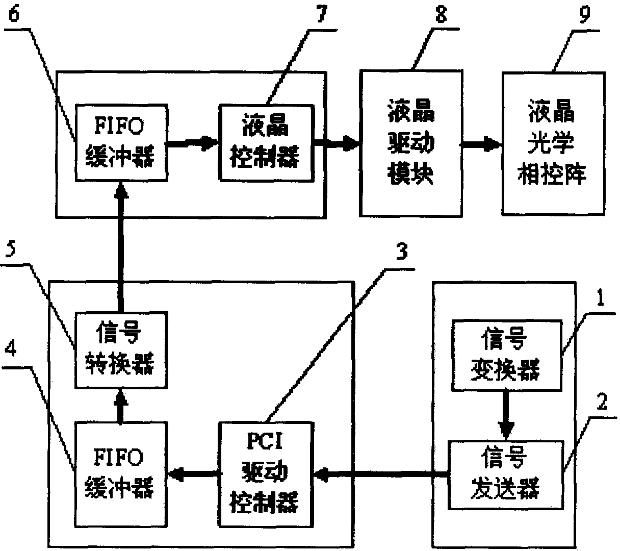
[0016] The transmission type liquid crystal optical phased array drive control system of the present invention, the signal converter 1, the signal transmitter 2 are VC programs running in the operating system of the PC; the PCI drive controller 3, the FIFO buffer 4, the signal converter 5 It is a Verilog program running inside the data acquisition card; FIFO buffer 6 and liquid crystal controller 7 are Verilog programs running inside the FPGA target board. Among them, the signal converter 1 is used to input the orientation angle control signal of the liquid crystal optical phased array 9 and convert it into a digital voltage control signal; the signal transmitter 2 is used to package the digital voltage control signal output by the signal converter 1 It is a two-dimensional array structure and sent to the PCI driver controller 3 through the PCI bus; the PCI driver controller 3 is used to receive the digital voltage control signal data packet output by the signal transmitter 2, ...


PUM


Abstract

The invention relates to a transmissive liquid crystal optical phased array drive and control system, which mainly includes a signal converter 1 and a signal transmitter 2 which are VC programs running in the operating system of a PC; a PCI drive controller 3 and a FIFO buffer 4. The signal converter 5 is a Verilog program running inside the data acquisition card; the FIFO buffer 6 and the liquid crystal controller 7 are Verilog programs running inside the FPGA target board. The transmission type liquid crystal optical phased array drive control system of the present invention, through the high-precision control and sampling of the voltage input end of each pixel electrode, the high-speed switching and accurate control of multi-channel signals, has high orientation accuracy and orientation speed, and is a transmissive The liquid crystal optical phased array provides a drive and control system that can be used in practice, and lays the foundation for the realization of the transmissive liquid crystal optical phased array equipment.

Description

technical field [0001] The invention relates to a drive and control system for a transmissive liquid crystal optical phased array, which belongs to the field of optomechanical integration technology. Background technique [0002] With the development of high technology, offensive weapons are developing in the direction of fast, small and stealthy, and the trend of accelerated development is obvious. For example, the hypersonic missiles and hypersonic aircraft being researched by Western military powers will form combat effectiveness within 5 to 10 years. Such weapons are fast. If missiles, artillery or powerful lasers are used for interception, it is often necessary to detect and identify targets tens of kilometers or even hundreds of kilometers away. Existing tactical radars can no longer meet the requirements. [0003] Due to the short laser wavelength, LiDAR is an ideal equipment for early warning and identification of small targets within 100 kilometers. However, the l...

Claims


Application Information

Patent Timeline
Patent Type & Authority Patents(China)
IPC IPC(8): G02F1/133
Inventor 王鹏尹聿海史俊锋李晔徐林陆成强孙鑫鹏李松柏李川杨振张帆张马驰蔡岳
Owner CHINA WEAPON EQUIP RES INST
Learn More