Automated system for detection and control of water leaks, gas leaks, and other building problems

a technology for automatic system and water leak detection, applied in the direction of fluid leakage detection, fluid tightness measurement, instruments, etc., can solve the problems of undesirable water, gas or other substances entering the building, occupants' health hazards, and parts of these networks that require periodic maintenan

Inactive Publication Date: 2006-08-31
GARABEDIAN MICHAEL +1
View PDF25 Cites 32 Cited by
  • Summary
  • Abstract
  • Description
  • Claims
  • Application Information

AI Technical Summary

Benefits of technology

[0014] The present invention is a system for remotely monitoring and responding to different types of detected leaks. It includes a plurality of sensors at locations of possible leaks. The sensors transmit signals upon leak detection. A control device receives the transmitted signal and determines an appropriate response to the detected leak. The control device functions to perform the desired response. According to a...

Problems solved by technology

The parts in these networks often require periodic maintenance.
Not infrequently, there is a malfunction and undesirable water, gas or other substances leak into the building.
These leaks present a health hazard to the occupants and cause significant damage to the building and its contents.
Often, the occurrence of a leak is not noticed until sufficient water or other substance has accumulated in an occupied area.
Since the network of pipes is generally located out of sight, a substantial leak, with accompanying damage, will have occurred before its occurrence is detected.
Failures also occur at the fixture or appliance which also may cause a leak.
Failures within the network are often caused by ambient conditions which cause the water in certain pipes, such as pipes extending through or along poorly-insulated outside walls, to freeze, bursting the pipes.
Serious flooding is also often caused by inadvertently leaving a faucet in a sink or tub running with the associated drain blocked.
Additionally, in buildings which are heated, there is a constant danger that lethal carbon monoxide will be generated from improper combustion of the fuel source.
While the locations of potential ...

Method used


Image

  • Automated system for detection and control of water leaks, gas leaks, and other building problems
  • Automated system for detection and control of water leaks, gas leaks, and other building problems

Examples


Embodiment Construction

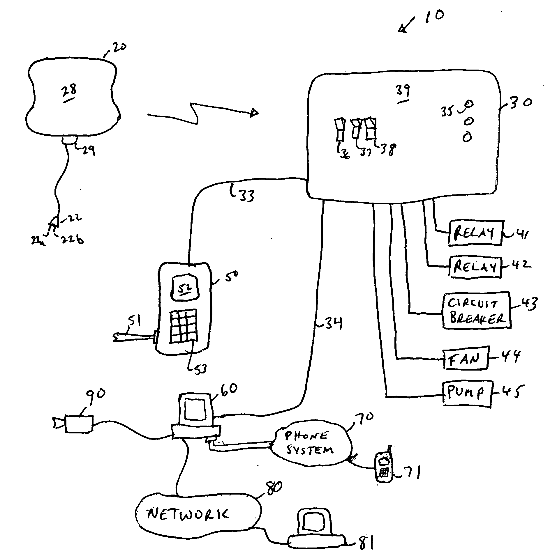
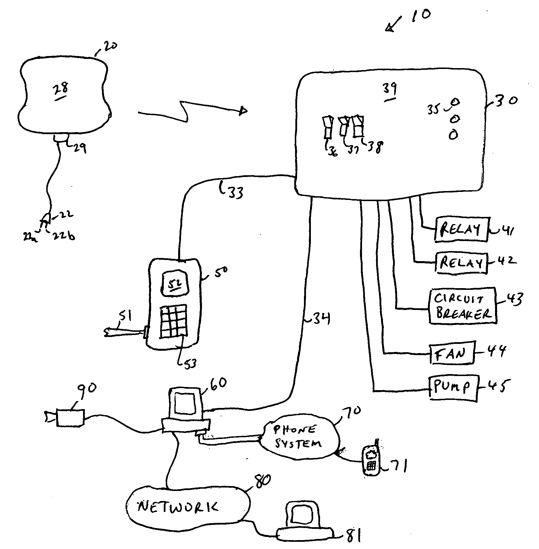
[0018] The present invention is a “smart” system allowing multiple possible responses to detection of leaks and remote control of system parts. The present applicants filed on even date herewith a U.S. Patent Application entitled “Automated System For Detection And Control Of Water Leaks, Gas Leaks, And Other Building Problems”, incorporated herein by reference in its entirety, which relates to a system for detecting and selectively responding to leaks. That system includes a plurality of sensors for detecting leaks. Each sensor includes an identifier. When a leak is detecting, the sensor transmits a signal, including its identifier, to a control device. The control device performs different actions based upon the identifier of the sensor which detected a leak. The present invention extends this system to provide additional user control. Specifically, the system of the present invention connects the control device to a computer or other processing system. The computer or processing ...


PUM


Abstract

A leak detection and control system provides for remote user control of devices in responding to detected leaks of other problems. A plurality of sensors and sensor types are used at various locations in a building where leaks are likely to occur. Upon detection of a leak, a sensor sends an RF signal identifying the sensor. A controller receives the RF signal and performs actions associated with the identifier for the sensor. Actions may include selectively closing or opening valves and electrical connections. Notifications are also sent by the system to building owners, occupants, maintenance personnel or operators. An operator can contact the controller from a remote location via a telephone system or a network to check status and to activate devices.

Description


Claims


Application Information

Patent Timeline
IPC IPC(8): G01M3/04G08B21/00
CPCF17D5/06G08B21/12G08B21/20
Inventor GARABEDIAN, MICHAELGARABEDIAN, PATRICK
Owner GARABEDIAN MICHAEL
Why Eureka
Try Eureka