Gearset, in particular for electric hand machine tools

a technology for electric hand machine tools and gear sets, which is applied in the direction of gearing, portable power-driven tools, hoisting equipment, etc., can solve the problems of loud running noise, only delivering low torque, and adversely affecting the service li

Inactive Publication Date: 2006-08-31
ROBERT BOSCH GMBH
View PDF6 Cites 10 Cited by
  • Summary
  • Abstract
  • Description
  • Claims
  • Application Information

AI Technical Summary

Problems solved by technology

Plastic gear wheels, which can be produced at a similar cost to sintered gear wheels, can transmit only low torques and are therefore used in hand power tools only in a few exceptional cases.
Pairs of gear wheels put together from sintered gear wheels have the disadvantage, dictated by their production, of major tolerances, which causes loud running noise and has an adverse effect on the service life.

Method used


Image

  • Gearset, in particular for electric hand machine tools
  • Gearset, in particular for electric hand machine tools
  • Gearset, in particular for electric hand machine tools

Examples


Embodiment Construction

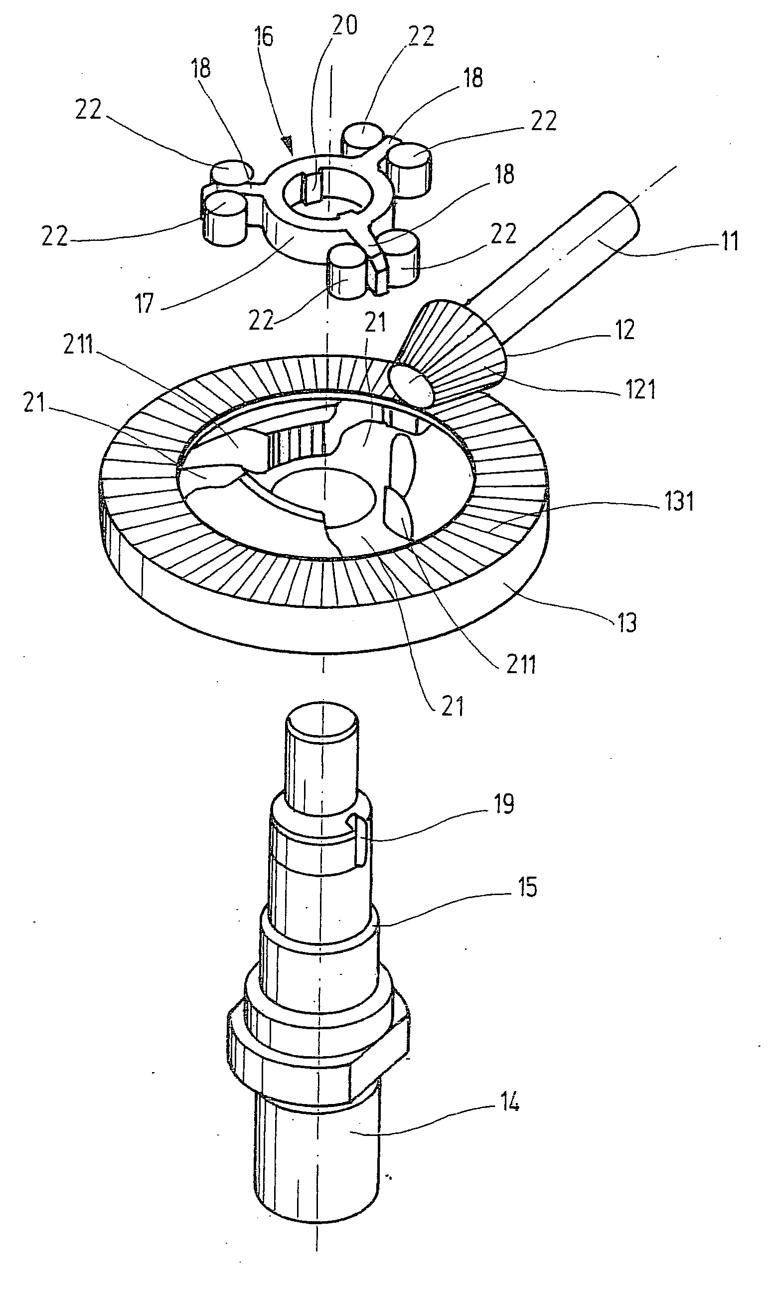
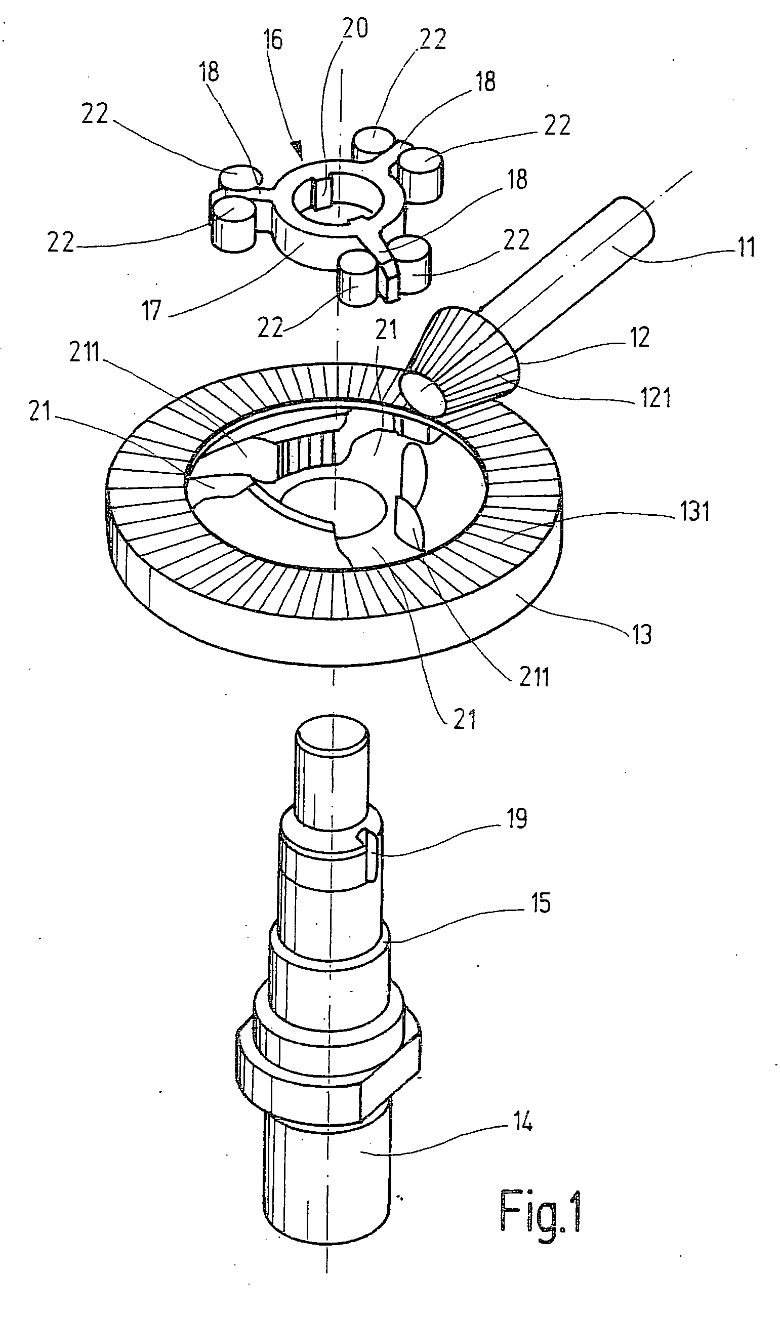
[0012] The angular gear, sketched in an exploded view in FIG. 1, for a hand power tool as an exemplary embodiment for a gear mechanism in general has a drive shaft 11, which can be driven by an electric motor; a driving gear wheel 12, seated in a manner fixed against relative rotation on the drive shaft 11 and embodied here as a conical pinion with pinion gearing 121; a driven gear wheel 13 meshing with the driving gear wheel 12, which driven gear wheel is embodied as a ring gear with spur gearing 131; and a driven shaft 14, driven by the driven gear wheel 13. The driven gear wheel 13 sits without play, rotatably and axially nondisplaceably, on the driven shaft 14; in the axial direction, it is braced on one side on an annular shoulder 15 (FIG. 1) embodied on the driven shaft 14 and on the other on a slaving device 16, which is pressed onto the driven shaft 14 and is additionally joined by force-locking to the driven shaft 14. The slaving device 16 has both a ring 17, surrounding th...


PUM


Abstract

A gear mechanism, in particular for hand power tools, is disclosed which has a driving gear wheel (12), seated on a drive shaft (11) in the manner fixed against relative rotation, and a driven gear wheel (13), meshing with the driving gear wheel and driving a driven shaft (14). To attain high running smoothness of the gear mechanism and a longer service life by reducing the mechanical load on the gearing upon startup and in load peaks that occur during operation, spring-elastic damping elements (22) are located between the driven gear wheel (13) and the driven shaft (14) (FIG. 2).

Description

PRIOR ART [0001] The invention is based on a gear mechanism, in particular for hand power tools, as generically defined by the preamble to claim 1. [0002] In gear mechanisms for hand power tools, sintered gear wheels with a spiral or straight gearing are used, for reasons of cost. Recourse to gear wheels that are cut, whose production costs are relatively high, is had only whenever stringent demands for running smoothness are made, in the case of high-quality appliances. Plastic gear wheels, which can be produced at a similar cost to sintered gear wheels, can transmit only low torques and are therefore used in hand power tools only in a few exceptional cases. [0003] Pairs of gear wheels put together from sintered gear wheels have the disadvantage, dictated by their production, of major tolerances, which causes loud running noise and has an adverse effect on the service life. ADVANTAGES OF THE INVENTION [0004] The gear mechanism of the invention, in particular for hand power tools, h...

Claims


Application Information

Patent Timeline
Patent Type & Authority Applications(United States)
IPC IPC(8): F16H55/14B25F5/00F16F15/124F16H1/14F16H57/00
CPCB25F5/001F16F15/124Y10T74/19633F16H55/14F16H57/0006F16H1/14
Inventor STIERLE, PETERWIKER, JUERGENSCHADOW, JOACHIM
Owner ROBERT BOSCH GMBH
Why Eureka
Try Eureka