Toroidal rotary damping apparatus

a rotary damping and rotating technology, applied in the direction of shock absorbers, springs/dampers, liquid resistance brakes, etc., can solve the problems of non-uniform sealing, substantial frictional losses, inherent characteristics of traditional vane-type rotary dampers, etc., and achieve the effect of superior sealing properties

Inactive Publication Date: 2006-08-31
MORADIAN NORICK B
View PDF0 Cites 25 Cited by
  • Summary
  • Abstract
  • Description
  • Claims
  • Application Information

AI Technical Summary

Benefits of technology

[0007] The present invention relates to a rotary damper apparatus which has a number of advantages over prior art damper constructions. The rotary damper apparatus is assembled within a toroidal ...

Problems solved by technology

Traditional vane-type rotary dampers have inherent disadvantages, including the following:
Hysteresis: Due to disproportionate vane seal pre-load; caused by means such as compression springs, long elastomer seals, band springs and composite seal springs, resulting in substantial frictional losses, non-uniform sealing and curtailed dynamic range.
Excessive Leakage: As rotary vane damper housing is subject to hoop stress and side-load deformation, additionally, the vane is subject to bending strain at tip extremities, resulting in excessive bypass leakage flow and ensuing loss of fluid pressure.
Thermal hysteresis: This is due to non-uniform coefficient of expansion of damper housing and vane contact surfaces; exasperated by long linear sealing contours of the vane with mating surfaces, leading to unstable damping characteristics, also known as “fade” over the operating temperature ranges.
This limits the effective operating temperature span and diminishes damping efficiency during thermal cycle.
Furthermore, such prior art devices are hampered by their relative complexity, size, weight and high cost.
All of the above measures reduce damping efficien...

Method used


Image

  • Toroidal rotary damping apparatus
  • Toroidal rotary damping apparatus
  • Toroidal rotary damping apparatus

Examples


Embodiment Construction

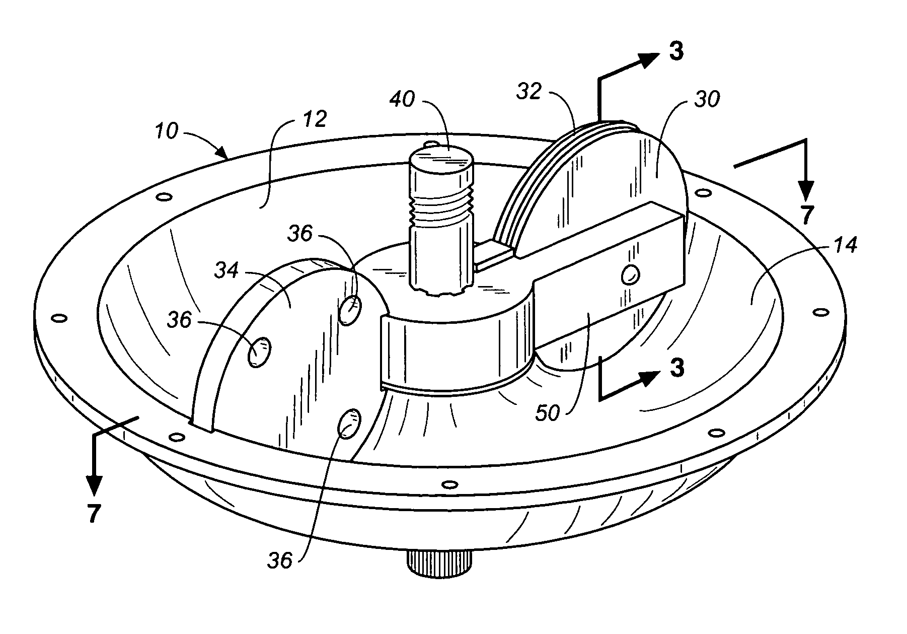
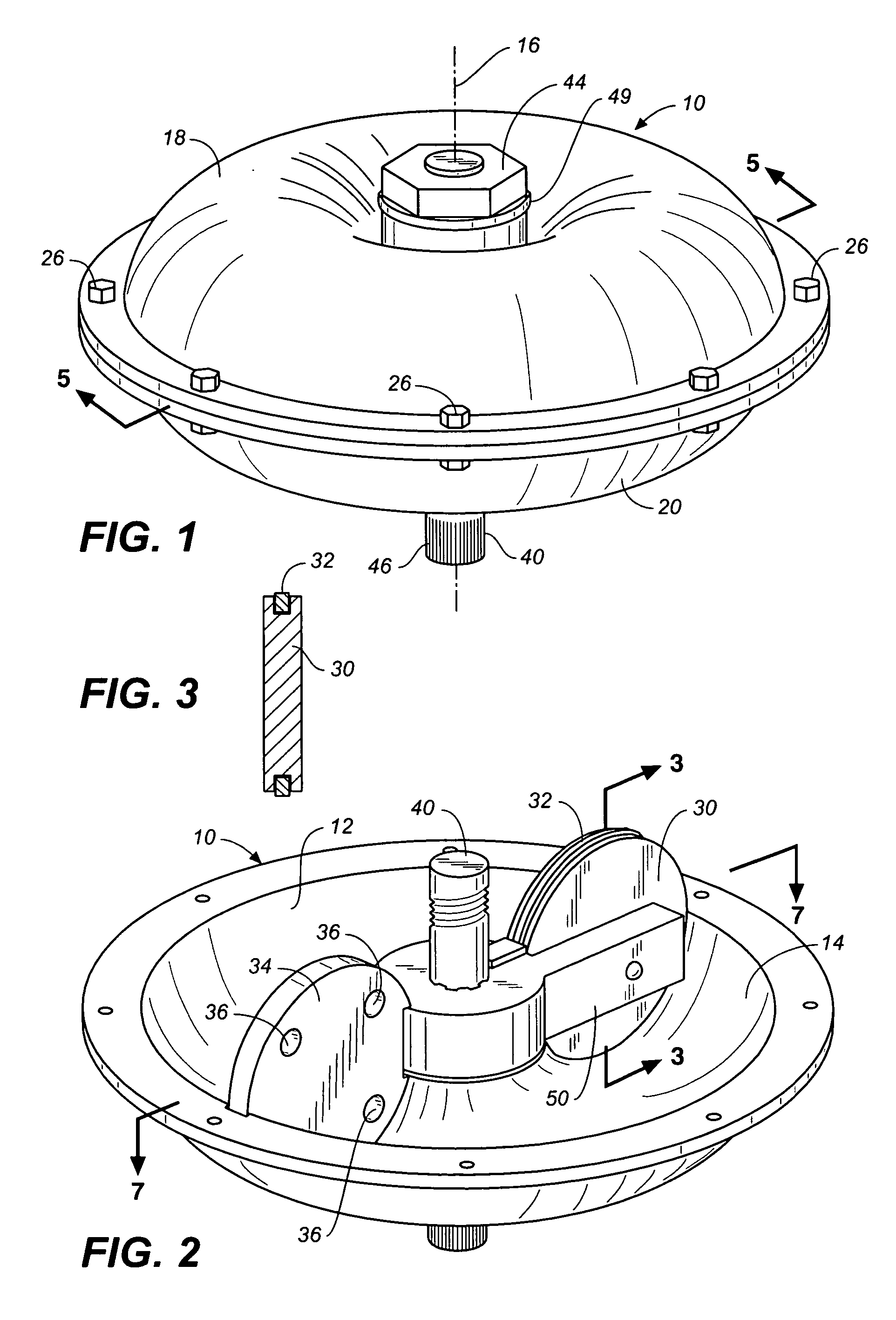
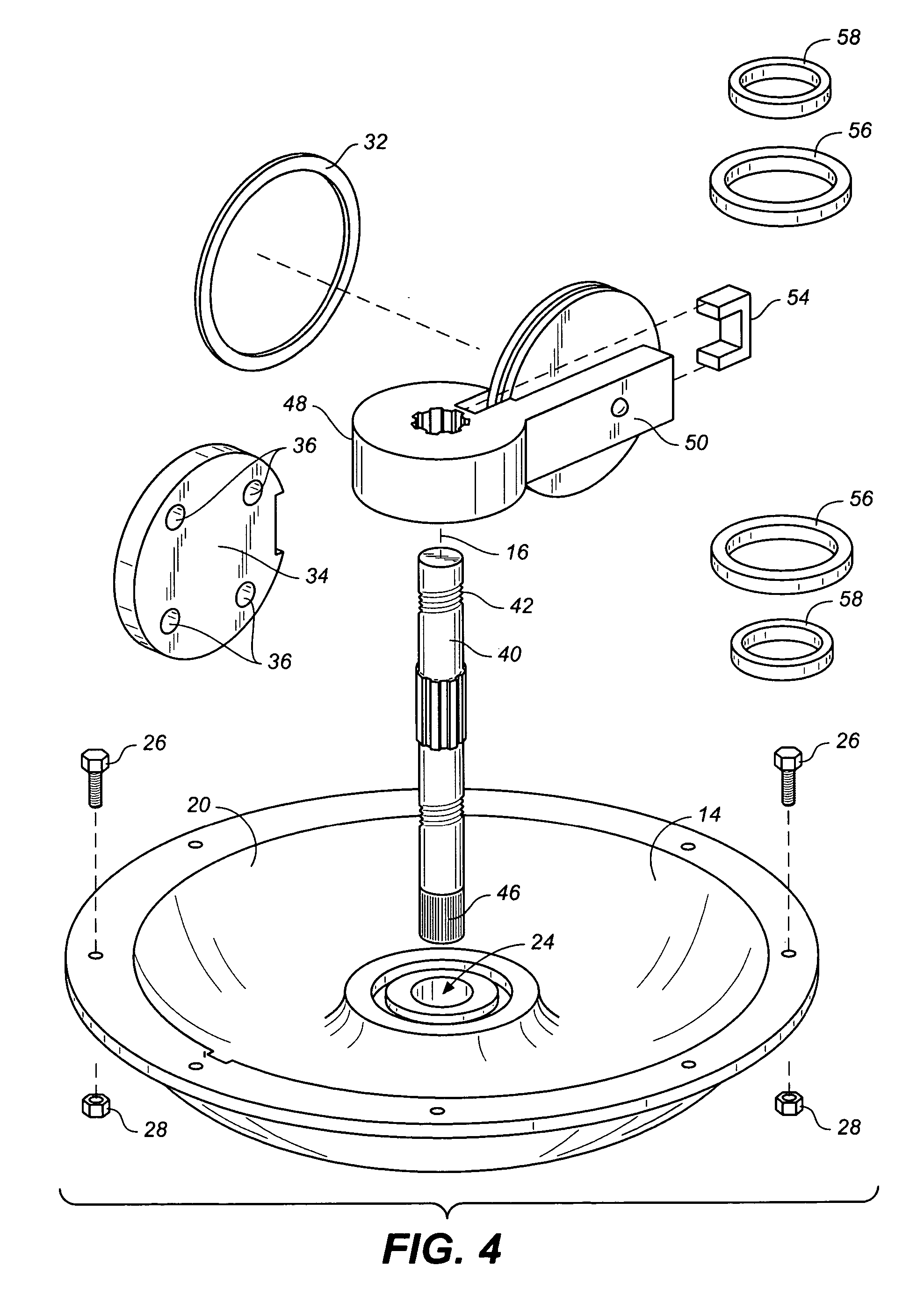
[0230] Referring now to FIGS. 1-6 and 22-26, wherein like reference numerals refer to like components in the various views, there is illustrated therein a new and improved toroidal rotary damper apparatus illustrated in accordance with the teachings of the present invention. The apparatus includes a housing 10 defining a housing interior 12 for containing damper fluid (not shown) of any conventional nature. The housing interior has a substantially circular cross section and is formed by a toroidal inner housing surface 14 disposed about and spaced from a central axis 16.

[0231] The housing 10 comprises two adjoining housing members 18, 20, each housing member defining a portion of the housing interior and further defining openings 22, 24, respectively, at the centers thereof. Threaded fasteners 26 extending through holes in outer flanges of the housing members are utilized to releasably secure the housing members together.

[0232] A disc-shaped piston 30 having a substantially circul...


PUM


Abstract

A toroidal rotary damper apparatus includes a housing having a partial toroidal inner housing surface and a piston moveable in the housing having a curved outer peripheral piston surface in engagement with the inner housing surface. The housing includes terminal ends defining fluid barriers. A flow control passageway defined by either the piston or an external control system controls passage of damper fluid when there is relative rotational movement between the piston and the housing to dampen the forces causing relative rotational movement.

Description

CROSS REFERENCES TO RELATED APPLICATIONS [0001] The present application claims the benefit of U.S. Utility Patent Application Ser. No. 10 / 294,019, filed 11 / 12 / 2002 (Nov. 12, 2002).SEQUENCE LISTING [0002] Not applicable. STATEMENT REGARDING FEDERALLY SPONSORED RESEARCH OR DEVELOPMENT [0003] Not applicable. THE NAMES OR PARTIES TO A JOINT RESEARCH AGREEMENT [0004] Not applicable. INCORPORATION-BY-REFERENCE OF MATERIAL SUBMITTED ON A COMPACT DISC [0005] Not applicable. BACKGROUND OF THE INVENTION [0006] 1. Field of the Invention: [0007] The present invention relates to a rotary damper apparatus which has a number of advantages over prior art damper constructions. The rotary damper apparatus is assembled within a toroidal housing and has superior sealing properties due to the constant engagement between a disc-like circular piston and the interior of a housing shaped in a full or partial toroid (or torus or anchor ring). [0008] 2. Discussion of Related Art including information disclose...

Claims


Application Information

Patent Timeline
IPC IPC(8): F16D57/02
CPCF16F9/145F16F9/466F16F9/44F16D57/02
Inventor MORADIAN, NORICK B.
Owner MORADIAN NORICK B
Why Eureka
Try Eureka