High frequency heating device with steam generating function

Inactive Publication Date: 2006-08-31
PANASONIC CORP
View PDF9 Cites 17 Cited by
  • Summary
  • Abstract
  • Description
  • Claims
  • Application Information

AI Technical Summary

Benefits of technology

[0024] From the viewpoint of preventing occurrence of non-uniform heating of heating steam in the heating chamber of the high frequency heating apparatus, it is desirable that steam generators each comprising the water supply tray and the heating means are dispersively equipped at plural places in the heating chamber to uniformly supply heating steam in the heating chamber. However, if the steam generators are dispersively equipped at the plural places, it is needed to uniformly supply water to the water supply trays at the plural places.
[0025] Therefore, when plural pairs of water supply trays and heating means are equipped as described above, if the distance from the heating area based on the heating means to a water blow-out port at the tip of each water supply path equipped every water supply tray is set to be equal among the water supply paths, the water supply amounts through the water supply

Problems solved by technology

However, only the heating based on the high frequency heating limits the range of cooling or the like, and thus it has been inconvenient.
The steam supply mechanism of the conventional high frequency heating apparatus is designed to be equipped with a water tank detachably secured to the main body of the apparatus, a water supply tray mounted in the heating chamber, heating means for heating the water supply tray and vaporizing water on the water supply tray, and dedicated pump means for supplying water in the water tank to the water supply tray, and the equipment of the pump means causes a problem that the construction of the apparatus

Method used


Image

  • High frequency heating device with steam generating function
  • High frequency heating device with steam generating function
  • High frequency heating device with steam generating function

Examples


Embodiment Construction

[0041] A high frequency heating apparatus having a steam generating function according to an embodiment of the present invention will be described hereunder in detail with reference to the accompanying drawings.

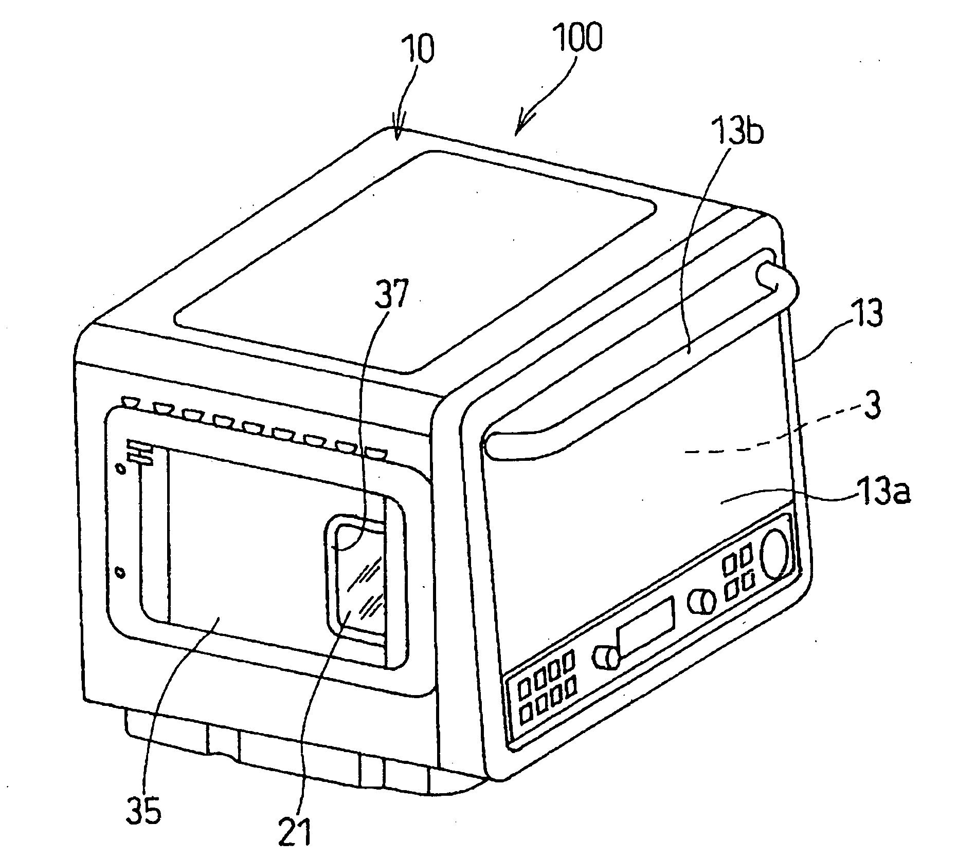
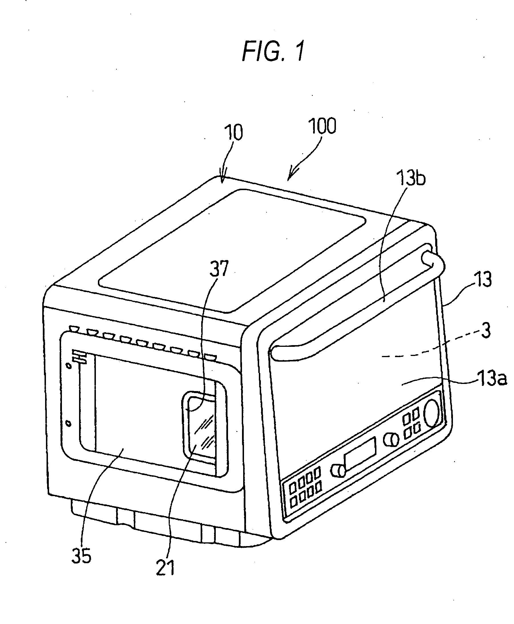
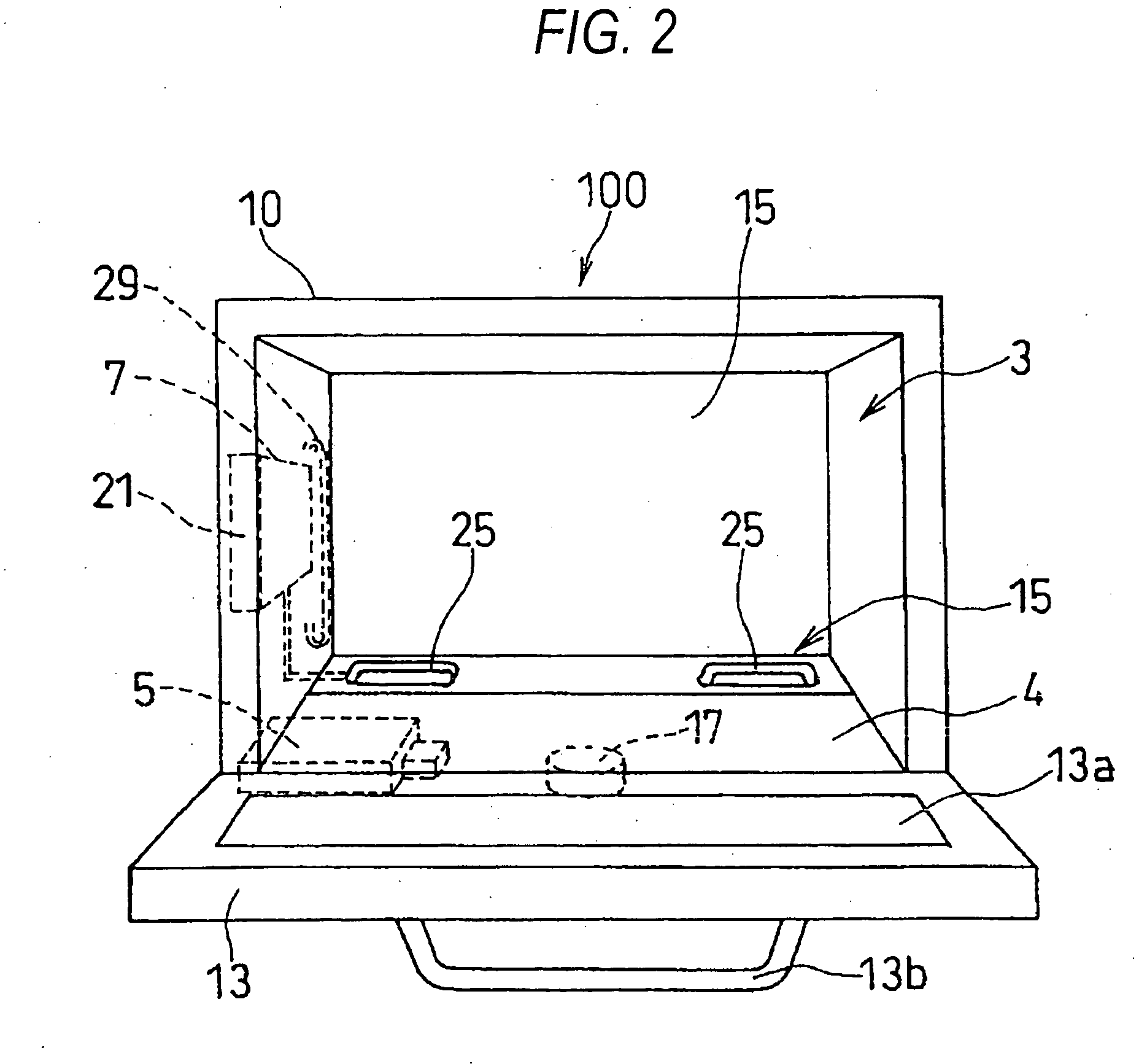
[0042]FIGS. 1 and 2 are diagrams showing the outlook of an embodiment of a high frequency heating apparatus having a steam generating function according to the present invention.

[0043] The high frequency heating apparatus 100 having the steam generating function according to the embodiment of the present invention is used as an electronic oven that can carry out heating with high frequency heating and heating steam for cooking of foodstuff. The high frequency heating apparatus 100 is equipped with high frequency wave generating means (magnetron) 5 for outputting a high frequency wave into a heating chamber 3 in which heat target such as foodstuff or the like is accommodated, and a steam supply mechanism 7 for supplying heating steam into the heating chamber 3, and supplies ...


PUM


Abstract

The object of the present invention is to achieve a high frequency heating apparatus having a steam generating function that can implement simplification and miniaturization of the construction of a steam supply mechanism by omitting dedicated pump means for supplying water of a water tank.
In a high frequency heating apparatus having a steam generating function (100), a steam supply mechanism (7) for supplying heating steam into a heating chamber (3) is constructed by a water tank (21) detachably equipped to the main body of the apparatus, water supply trays 825), (25) mounted in the heating chamber (3), heating means (27), (27) for vaporizing water on the water supply trays (25), (25) by heating the water supply trays (25), (25), and water supply paths (29), (29) for leading water in the water tank (21) through heating areas based on the heating means (27), (27) to the water supply trays (25), (25), and the water in the water tank (21) is supplied to the water supply trays (25), (25) by using thermal expansion of water in the water supply paths (29), (29) which is caused by the heat generated in the heating means (27), (27).

Description

TECHNICAL FIELD [0001] The present invention relates to a high frequency heating apparatus equipped with high frequency generating means for outputting a high frequency wave into a heating chamber in which a heating target to be heated is accommodated and a steam supply mechanism for supplying steam into the heating chamber, and supplying at least one of the high frequency wave and the steam into the heating chamber to conducting a heating treatment on the heating target, and particularly to an improvement of implementing simplification and miniaturization of the construction of the steam supply mechanism. BACKGROUND ART [0002] A high frequency heating apparatus having a high frequency wave generating means for outputting a high frequency wave into a heating chamber in which a heating target to be heated is accommodated can efficiently heat the heating target in the heating chamber in a short time, and thus it has become rapidly widespread as a microwave oven which is a cooling inst...

Claims


Application Information

Patent Timeline
IPC IPC(8): H05B6/64F22B1/28F24C1/00F24C7/02F24C15/00H05B6/80
CPCF24C15/003H05B6/6479
Inventor KANZAKI, KOUJIHAYAKAWA, YUJI
Owner PANASONIC CORP
Why Eureka
Try Eureka