Motor Controlling method and apparatus thereof

a motor and control method technology, applied in the direction of electric controllers, dynamo-electric gear control, dynamo-electric converter control, etc., can solve the problems of increased cost, inability to control with more accuracy, and inability to achieve phase shift, etc., to suppress the speed change, control with more accuracy, and improve stability

Inactive Publication Date: 2006-08-31
DAIKIN IND LTD
View PDF20 Cites 12 Cited by
  • Summary
  • Abstract
  • Description
  • Claims
  • Application Information

AI Technical Summary

Benefits of technology

[0024] In a ninth aspect of the present invention, a motor controlling method controls the voltage or current not to exceed a current maximum value of power devices of the inverter by reducing the amplitude of the output torque changing.
[0087] 3. The current peak can be reduced by weakening vibration suppression control when load is heavy, so that decrease in cost of motor inverter can be realized;

Problems solved by technology

When this method is employed, and when fidelity is improved, a disadvantage arises in that instability is realized in higher harmonics.
On the contrary, when fidelity is lowered, a disadvantage arises in that shifting in phase is realized.
When fidelity is improved, a disadvantage arises in that the current becomes too great, power devices and a motor with great capacity should be employed, thereby increase in cost is realized.
Therefore, a disadvantage arises for the former case in that an area is generated due to the changing of the instrument constants, within the area the motor cannot be driven.
A disadvantage arises for the latter case in that increase in cost is realized.
Particularly, when the voltage and current are controlled so as to cancel speed changing due to load torque changing, a disadvantage arises in that the processing for detecting a rotor position of a motor is possibly diverged.

Method used


Image

  • Motor Controlling method and apparatus thereof
  • Motor Controlling method and apparatus thereof
  • Motor Controlling method and apparatus thereof

Examples


Embodiment Construction

[0105] Hereinafter, referring to the attached drawings, we explain a motor controlling method and apparatus thereof of an embodiment according to the present invention in detail.

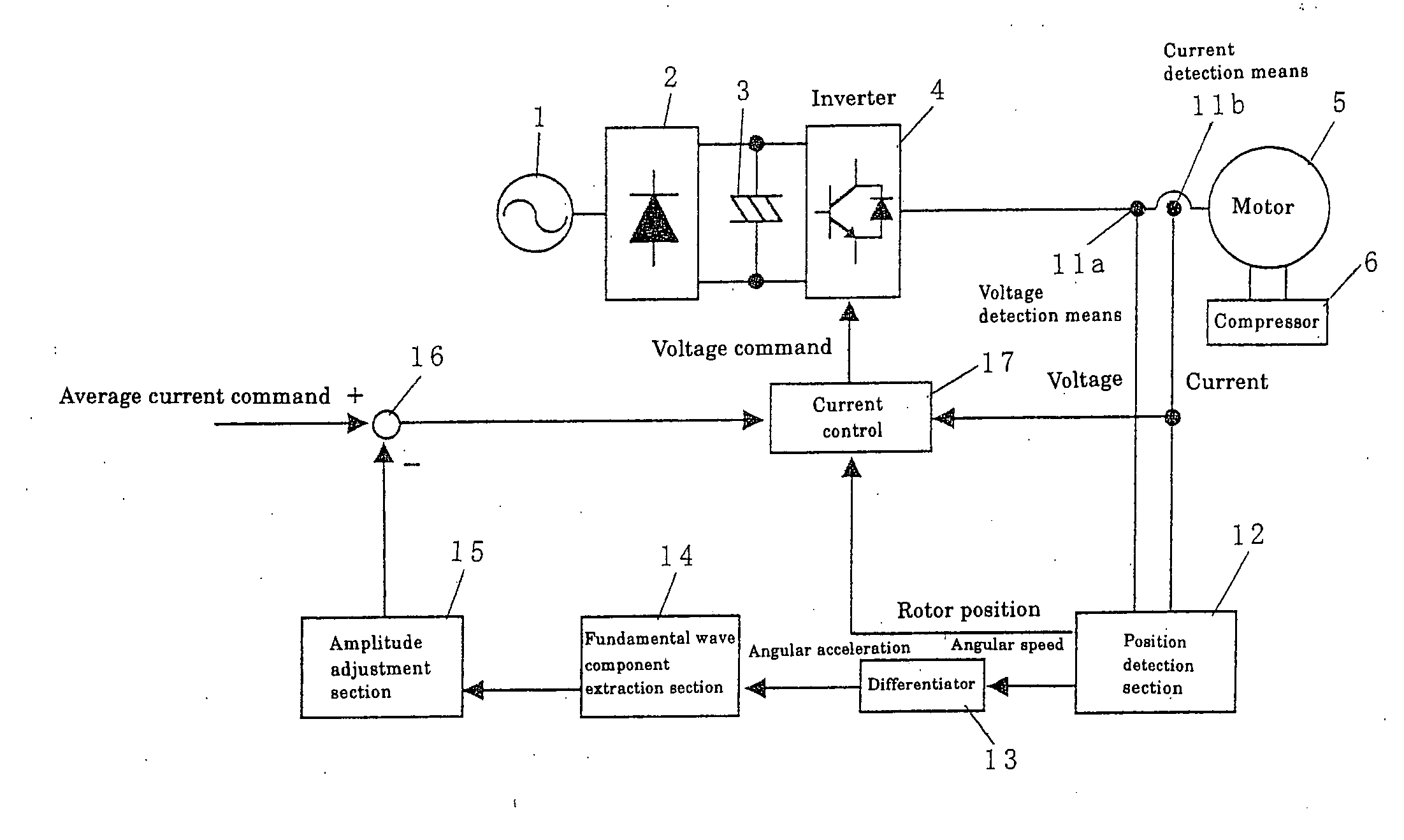
[0106]FIG. 1 is a block diagram illustrating a motor controlling apparatus of an embodiment according to the present invention.

[0107] In this motor controlling apparatus, a first AC power 1 is supplied to a converter 2 so that a DC power is obtained. The DC power is smoothened by a smoothing condenser 3. The smoothened DC power is converted into a second AC power by an inverter 4. The second AC power is supplied to a motor 5. And, a compressor 6 is driven by this motor 5.

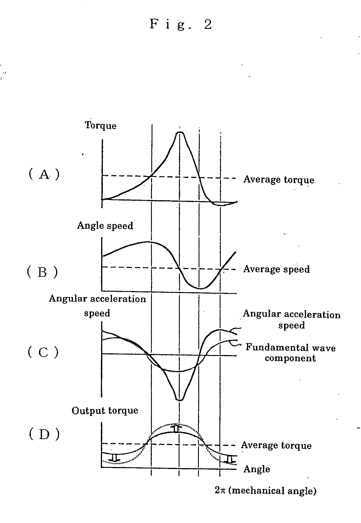
[0108] A voltage and current supplied to the motor 5 are detected by a voltage detection section 11a and a current detection section 1b, and are supplied to a position detection section 12. An angular speed output from this position detection section 12 is supplied to a differentiator 13 so that an angular acceleration is output, fundamen...


PUM


Abstract

A voltage detection section and current detection section detect a voltage and current supplied to a motor, and the detected voltage and current are supplied to a position detection section. An angular speed output from the position detection section is supplied to a differentiator to output an angular acceleration. A fundamental wave component extraction section extracts a fundamental wave component of the angular acceleration, and the extracted fundamental wave component is supplied to an amplitude adjustment section. The output of the amplitude adjustment section is subtracted from the average current command by a subtraction section. This subtraction result, current detection value, and the rotor position from the position detection section are supplied to a current control section to carry out the current control operation so as to obtain a current command. The current command is supplied to an inverter to control the voltage and current so as to suppress the speed changing due to the load torque changing. Thus, stability is improved, and a decrease in cost is realized.

Description

CROSS-REFERENCE TO RELATED APPLICATIONS [0001] This application is a divisional application of U.S. patent application Ser. No. 10 / 485,544 filed on Feb. 2, 2004. The entire disclosure of U.S. patent application Ser. No. 10 / 485,544 is hereby incorporated herein by reference.TECHNICAL FIELD [0002] The present invention relates to a method and apparatus for controlling a motor for driving a periodical load so as to suppress changing in its rotation speed. BACKGROUND ART [0003] From the past, a method is proposed for repetitively controlling a voltage, current so as to cancel a changing in speed due to a changing in load torque, as a method for controlling a motor for driving a periodical load so as to suppress changing in its rotation speed. [0004] When this method is employed, and when fidelity is improved, a disadvantage arises in that instability is realized in higher harmonics. On the contrary, when fidelity is lowered, a disadvantage arises in that shifting in phase is realized. [...

Claims


Application Information

Patent Timeline
Patent Type & Authority Applications(United States)
IPC IPC(8): G05F1/10H02P6/06H02P6/08H02P6/18H02P6/182H02P6/28H02P21/00H02P21/05H02P21/14H02P21/16H02P21/18H02P21/22H02P21/24H02P23/04H02P23/14H02P27/06
CPCH02P6/002H02P27/08H02P27/045H02P23/0036H02P23/0004H02P6/28H02P6/10
Inventor MAEDA, TOSHIYUKI
Owner DAIKIN IND LTD
Why Eureka
Try Eureka