Composite polymeric optical films with co-continuous phases

a polymer and phase-continuous technology, applied in the field of polymer optical films, can solve the problems of reducing the overall optical performance and cosmetic quality of optical films, difficulty in precisely positioning elements in more than one dimension, and lack of precision

Inactive Publication Date: 2006-08-31
3M INNOVATIVE PROPERTIES CO
View PDF78 Cites 72 Cited by
  • Summary
  • Abstract
  • Description
  • Claims
  • Application Information

AI Technical Summary

Benefits of technology

[0008] The above summary of the present invention is not intended to describe each illustrated embodiment or every implementatio

Problems solved by technology

A practical limitation of composite films, however, is that it is difficult to precisely position elements in more th

Method used


Image

  • Composite polymeric optical films with co-continuous phases
  • Composite polymeric optical films with co-continuous phases
  • Composite polymeric optical films with co-continuous phases

Examples


example

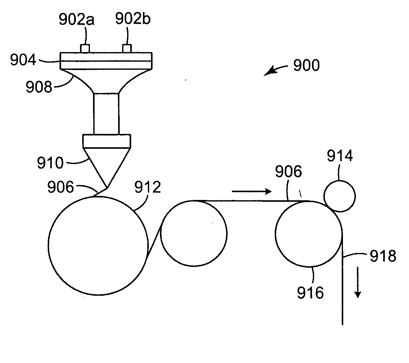
[0105] In an example of coextruding an element containing scattering fibers, a distribution plate, having one hundred and eighteen laser-machined plates and eleven end-milled plates, was assembled, having two input ports and about 1000 “island” ports. The feedblock was designed to achieve scattering fibers that have substantially equal polymer flow. A cross-section through the resulting coextruded element, in the form of a composite fiber, is shown in the photograph in FIG. 11. The composite fiber comprised a PEN (90%) / PET (10%) copolymer, as the scattering fiber “islands” in a matrix “sea” of a PETG copolyester, Eastar™ 6763, supplied by Eastman Chemical Co., Kingsport, Tenn. The extruded element had a diameter of about 200 μm. The extruded element was not stretched but, with stretching while maintaining geometric shape, could reach a diameter of around 25 μm, i.e., a reduction in diameter of around 87%. At such a stretch, the spacing between the scattering fibers would be about 50...


PUM

PropertyMeasurementUnit
Fractionaaaaaaaaaa
Fractionaaaaaaaaaa
Nanoscale particle sizeaaaaaaaaaa

Abstract

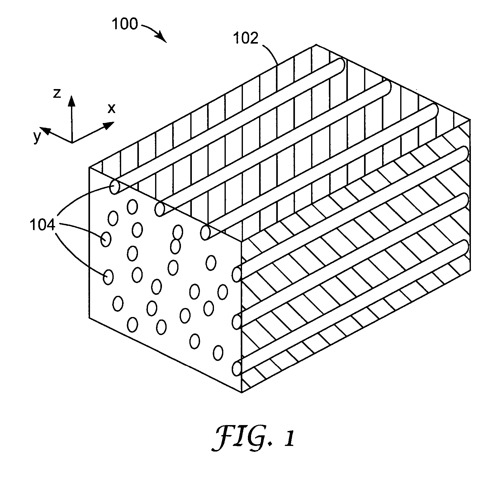
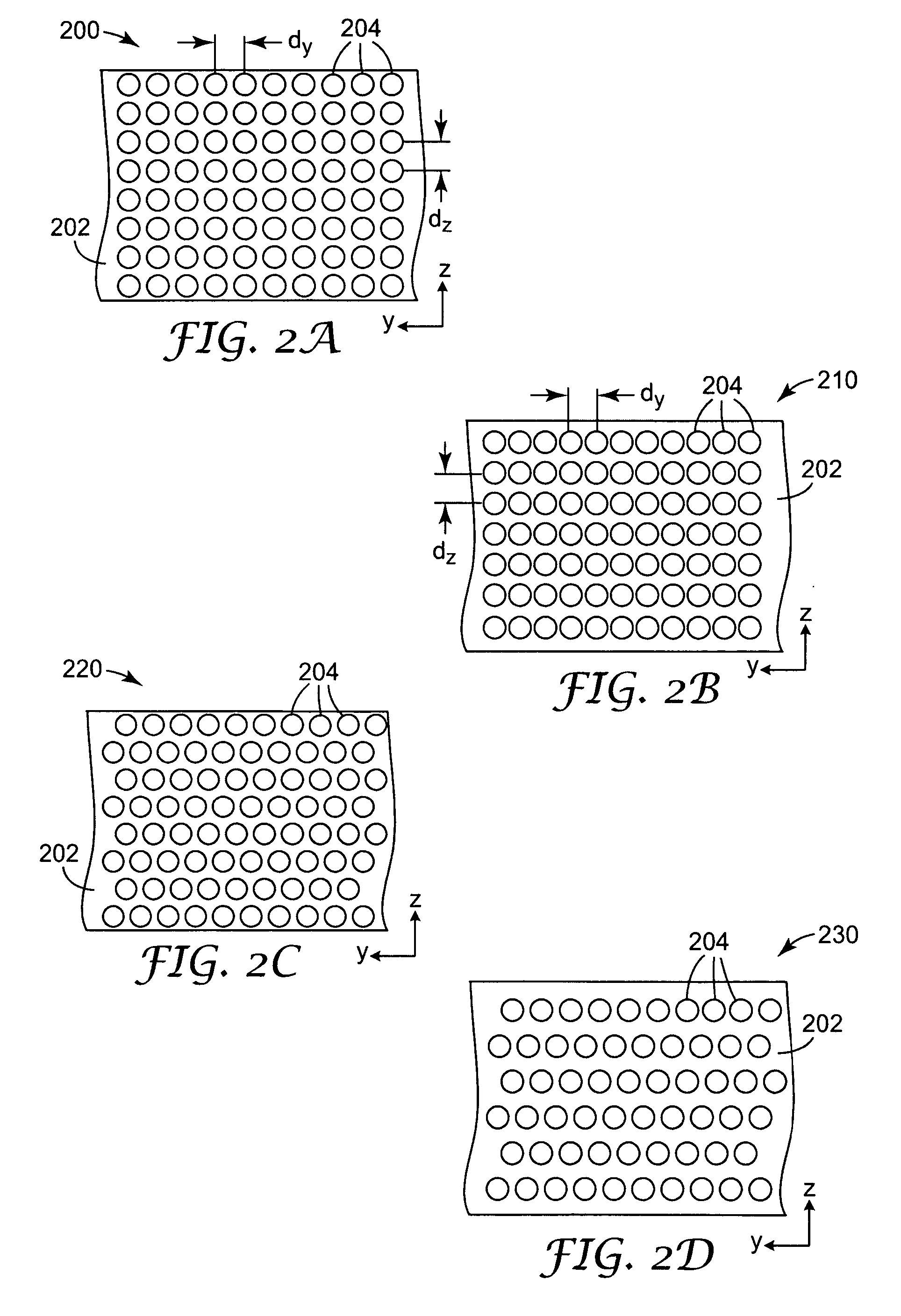
An optical element is formed by co-extruding to have an arrangement of polymer scattering fibers within a polymer matrix. The scattering fibers lie substantially parallel to a first axis. The scattering fibers are arranged at positions across the cross-section of the polymer matrix to scatter light transversely incident on the optical element in a direction substantially orthogonal to the first axis. The positions of the scattering fibers across the cross-section of the optical element may be selected so as to form a two-dimensional photonic crystal structure for light transversely incident on the optical element.

Description

RELATED APPLICATIONS [0001] This application is related to co-owned U.S. patent application Ser. No. ______, titled “REFLECTIVE POLARIZERS CONTAINING POLYMER FIBERS”, filed on even date herewith, having attorney docket no. 58959US002; Ser. No. ______, titled “COMPOSITE POLYMER FIBERS”, filed on even date herewith, having attorney docket no. 60371 US002; Ser. No. ______ titled “OPTICAL ELEMENTS CONTAINING A POLYMER FIBER WEAVE”, filed on even date herewith and having attorney docket no. 60622US002; Ser. No. ______ titled “POLYMER PHOTONIC CRYSTAL FIBERS”, filed on even date herewith and having attorney docket no. 60623US002; and Ser. No. ______, titled “POLYMERIC PHOTONIC CRYSTALS WITH CO-CONTINUOUS PHASES”, filed on even date herewith and having attorney docket no. 60624US002, all of which are incorporated herein by reference.FIELD OF THE INVENTION [0002] The invention relates to polymer optical film and more particularly to polymer optical film that provides selective properties fo...

Claims


Application Information

Patent Timeline
IPC IPC(8): G02B6/04B29C48/05B29C48/06
CPCB29C47/0004B29C47/0021B29C47/065B29C47/145B29C70/14B29K2105/06B29K2995/0018G02B5/0236G02B5/0257G02B5/0268G02B5/3008B29C48/022B29C48/08B29C48/21B29C48/307B29C48/06B29C48/05G02B6/032G02B5/20
Inventor OUDERKIRK, ANDREW J.BENSON, OLESTER JR.FLEMING, PATRICK R.KOPECKY, WILLIAM J.NORTH, DIANETHUNHORST, KRISTIN L.
Owner 3M INNOVATIVE PROPERTIES CO
Why Eureka
Try Eureka