Method of manufacturing an assembled body composed of a plurality of members, manufacturing method of electromagnetic control valve, and control valve for variable capacity compressors

a manufacturing method and assembly body technology, applied in machines/engines, positive displacement liquid engines, soldering devices, etc., can solve the problems of increasing the manufacturing cost of electromagnetic control valves, heat treatment, and assembly bodies that have been once subjected to brazing process can no longer be subjected, and achieve the effect of low cos

Inactive Publication Date: 2006-08-31
FUJIKOKI CORP
View PDF8 Cites 10 Cited by
  • Summary
  • Abstract
  • Description
  • Claims
  • Application Information

AI Technical Summary

Benefits of technology

[0015] The present invention has been made in view of the circumstances mentioned above and, therefore, an object of the present invention to provide a brazing method which makes it possible to rationally perform not only the brazing between a metal member such as a stator made of a magnetic material and a metal member such as a guide pipe made of a non-magnetic material but also the magnetic annealing of these metal members. Another object of the present invention is to provide a method of rationally and precisely manufacture an electromagnetic control valve provided with an assembled body comprising a stator, a guide pipe, a holder and a housing at low costs.
[0016] A further object of the present invention is to provide a control valve for a variable capacity compressor which can be employed in a crutch-attached compressor and which is capable of controlling the flow rate of cooling medium to be delivered from the cooling medium outlet port disposed on a downstream side of valve aperture to the crank chamber of compressor, thereby enabling the flow rate of cooling medium to be controlled so as not to exceed over an acceptable limit.

Problems solved by technology

The conventional method of manufacturing an electromagnetic control valve as described above is accompanied with the following problems.
(i) Since it requires the coupling and fixing work between the guide pipe 35 and the holder as well as between the holder and the housing in addition to the brazing work between the stator 33 and the guide pipe 35, a great deal of troublesome work and time are needed for assembling these assembled bodies, thus inevitably increasing the manufacturing cost of the electromagnetic control valve.
Further, the assembled body that has been once subjected to brazing process can no longer be subjected, as a matter of fact, to a heat treatment after the assembling thereof.
Therefore, there is a problem that when the assembled body includes a magnetic material, the magnetic property of the magnetic material cannot be sufficiently enhanced.
If the air gap “β” is left remained in this manner, the length of air gap between the sucking member to be secured to a lower end of the stator and the plunger becomes inappropriate, thus raising the problem that the control of flow rate cannot be appropriately performed.
In the case of the crutch-attached compressor however, when the control valve is caused to bring into the uncontrollable region, the pressure “Pc” inside the crank chamber exceeds over an allowable limitation, thereby raising problems in terms of control as well as in structural viewpoints.
Thus, the control valve for use in the crutch-less compressor cannot be utilized as it is in the crutch-attached compressor.

Method used


Image

  • Method of manufacturing an assembled body composed of a plurality of members, manufacturing method of electromagnetic control valve, and control valve for variable capacity compressors
  • Method of manufacturing an assembled body composed of a plurality of members, manufacturing method of electromagnetic control valve, and control valve for variable capacity compressors
  • Method of manufacturing an assembled body composed of a plurality of members, manufacturing method of electromagnetic control valve, and control valve for variable capacity compressors

Examples


first embodiment

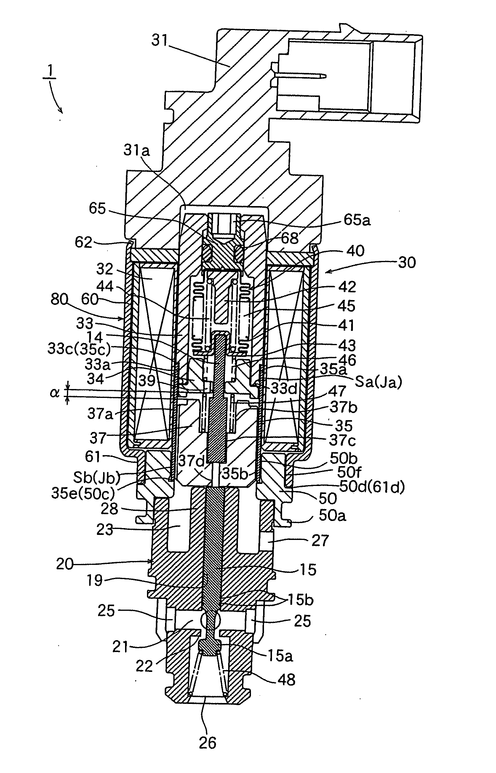
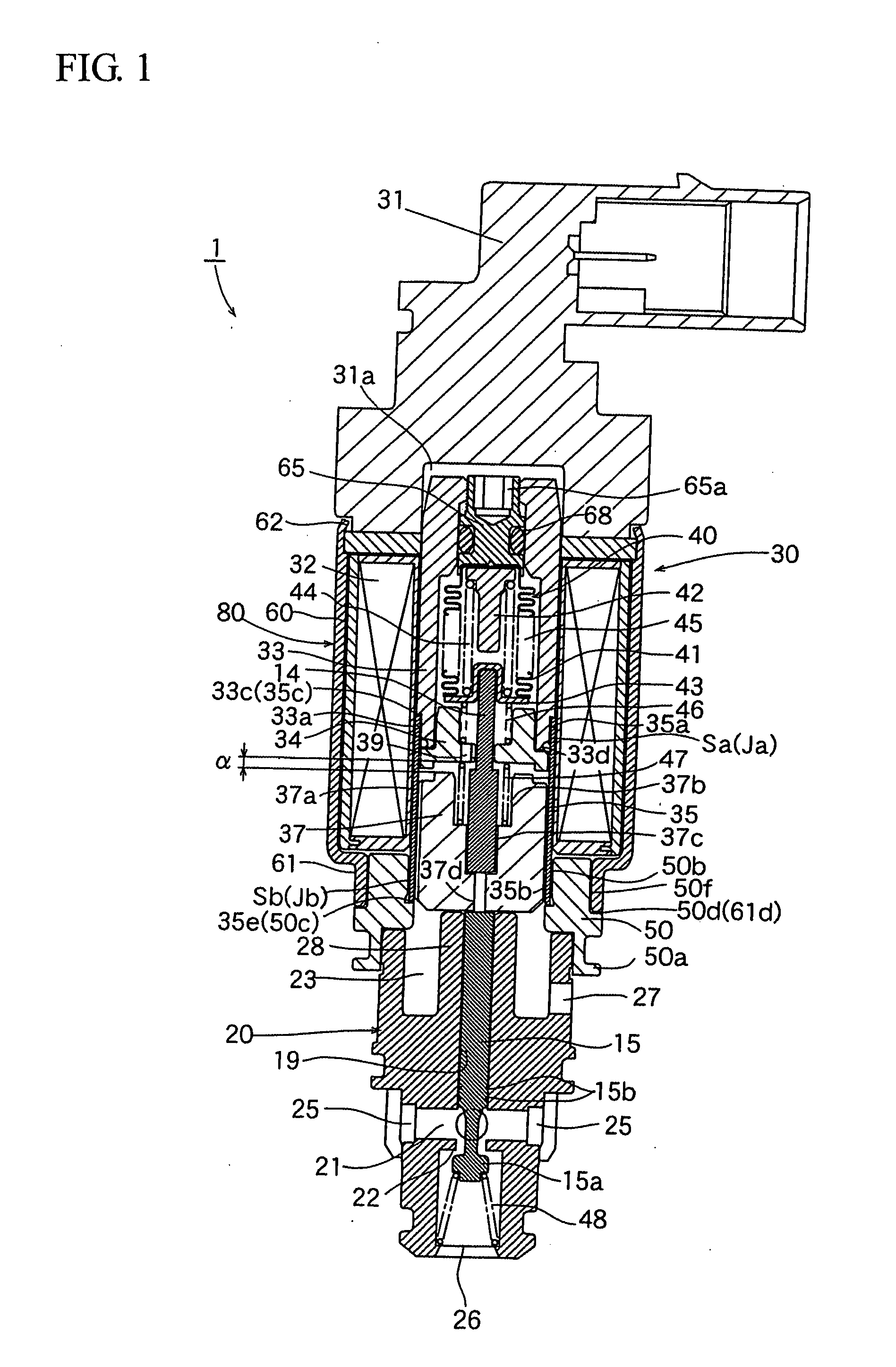
[0050]FIG. 1 shows a longitudinal sectional view illustrating one embodiment of the electromagnetic control valve for a variable capacity compressor, that has been manufactured according to the brazing method and manufacturing method representing one embodiment according to the present invention. In the following description, the construction of the electromagnetic control valve 1 will be explained at first, and then the method of manufacturing the electromagnetic control valve 1 will be explained.

[0051] The control valve I shown in FIG. 1 is equipped with a valve rod 15 having a valve body 1a; a valve main body 20 composed of a valve chamber 21 provided with a valve seat (valve aperture) 22 with which the valve body 1a can be retractivebly contacted, a plurality of inlet ports 25 for introducing a cooling medium of discharge pressure “Pd” from the compressor into the outer peripheral portion of the valve chamber 21 (on the upstream side of the valve seat 22), and a high pressure c...

second embodiment

[0071]FIG. 6 is a longitudinal sectional view illustrating a second embodiment of the control valve for a variable capacity type (crutch-attached) compressor according to the present invention.

[0072] The control valve 1′ for crutch-attached compressor shown in FIG. 6 is constructed such that a restricting mechanism (throttle aperture-attached closing member 70) to be described hereinafter is attached to a control valve for a crutch-less compressor. In other words, all of the components other than the restricting mechanism are the same as those of the crutch-less compressor. Next, the construction of the control valve 1′ will be explained in detail as follows.

[0073] The control valve 1′ comprises: a valve rod 15 having a valve body 15a having a +-shaped or T-shaped cross-section and attached to a lower end of the valve rod 15; a valve main body 20 provided with a valve chamber 21 having a valve aperture (valve seat) 22 with which the valve body 15a can be retractivebly contacted, w...

third embodiment

[0085] Next, a third embodiment of the control valve for a variable capacity type (crutch-attached) compressor according to the present invention will be explained.

[0086] The control valve 1″ according to this embodiment is the same in fundamental structure as that of the control valve 1′ of the second embodiment shown in FIG. 6 except that the magnitude of opening of valve (the magnitude of lift “L” from the valve aperture 22 of the valve body 15a (see FIG. 7)) is regulated in order to suppress the change in gradient of controlling pressure (see FIG. 8) that may be caused due to the provision of the throttle aperture-attached closing member 70 as a restricting mechanism.

[0087] Next, the construction of the control valve 1″ will be explained in detail as follows.

[0088] Due to the provision of the throttle aperture-attached closing member 70 as a restricting mechanism, when the value of electric current to be fed to the coil 32 becomes smaller than “Ia” which is close to zero (for...


PUM

PropertyMeasurementUnit
melting temperatureaaaaaaaaaa
electric currentaaaaaaaaaa

Abstract

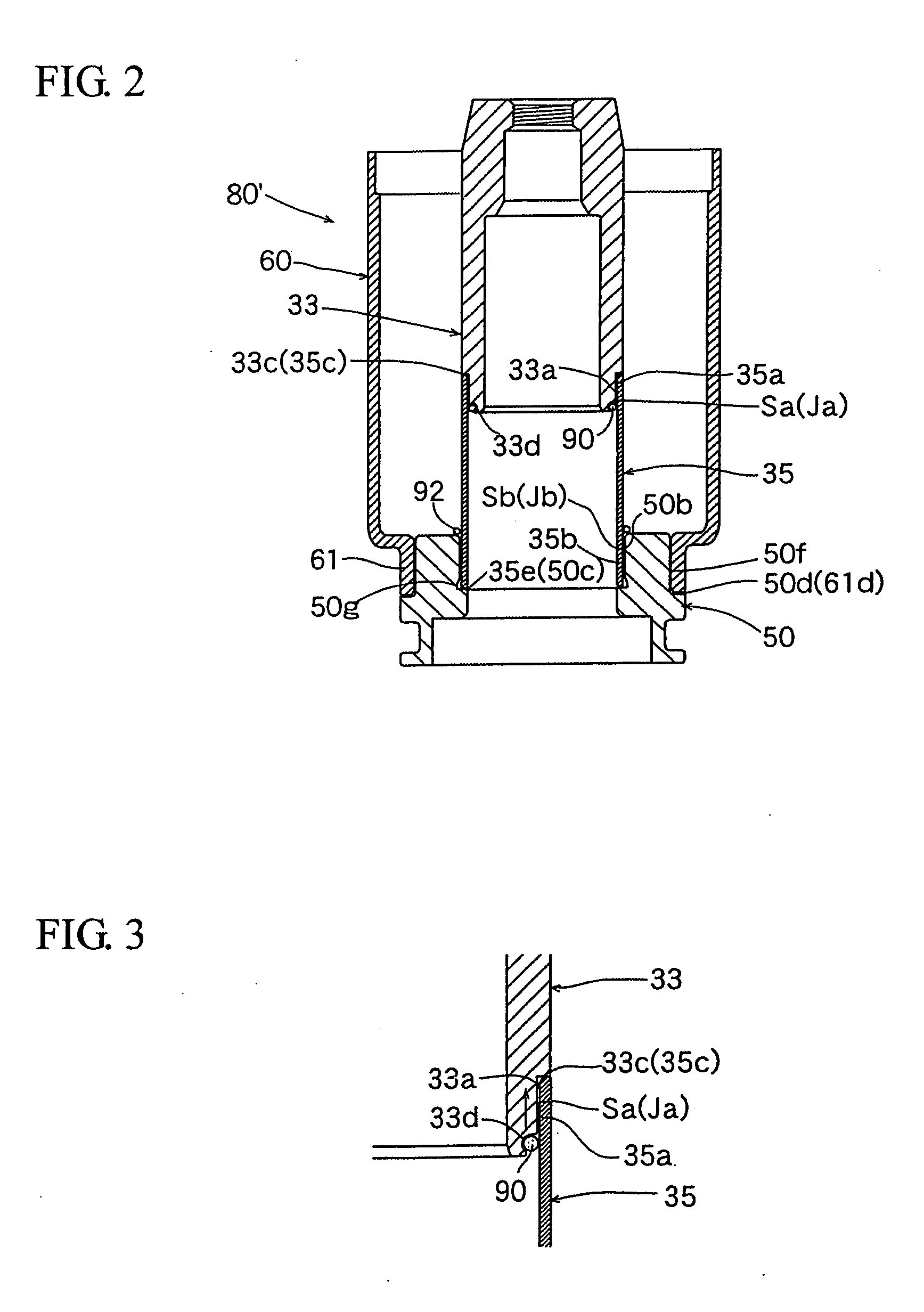
There is provided a brazing method which makes it possible to rationally perform not only the brazing between a metal member such as a stator made of a magnetic material and a metal member such as a guide pipe made of a non-magnetic material but also the magnetic annealing of these metal members. By making use of a brazing material (90) which can be fused at a lower temperature than a magnetic annealing temperature of metal member (33), the metal member such as a stator made of a magnetic material and the metal member (35) such as a guide pipe made of a non-magnetic material are heated to a predetermined temperature in a furnace to perform the magnetic annealing of the metal member (33) concurrent with the brazing of these metal members.

Description

BACKGROUND OF THE INVENTION [0001] 1. Field of the Invention [0002] The present invention relates to a method of manufacturing an assembled body composed of a plurality of components comprising a metallic member made of a magnetic material, and a metallic member made of a non-magnetic material. The present invention also relates to a method of manufacturing an electromagnetic control valve which is constituted by an assembled body wherein a stator made of a magnetic metallic material is fixedly coupled by means brazing to a guide pipe made of a non-magnetic metallic material and designed to be used as a plunger guide. [0003] Further, the present invention relates to a control valve for a variable capacity compressor to be employed in air conditioners for vehicle, in particular, to a control valve for a variable capacity compressor, which is suited for use in a crutch-attached compressor wherein the transmission of rotating driving force from the engine to the rotating axis of compre...

Claims


Application Information

Patent Timeline
Patent Type & Authority Applications(United States)
IPC IPC(8): F04B1/26
CPCB23K1/0008B23K35/30B23K2203/04C21D1/68C21D6/00F04B27/1804B23K2103/05B23K1/19
Inventor KUME, YOSHIYUKIIMAI, MASAYUKIKONDO, TATSUYAWATANUKI, TORU
Owner FUJIKOKI CORP
Why Eureka
Try Eureka