
Honeycomb structure

a honeycomb and structure technology, applied in the field of honeycomb structure, can solve the problems of deterioration of the isostatic strength affecting the performance of the honeycomb structure, so as to achieve a high porosity and hardly damage

Active Publication Date: 2006-08-31
NGK INSULATORS LTD
View PDF14 Cites 20 Cited by
  • Summary
  • Abstract
  • Description
  • Claims
  • Application Information

AI Technical Summary

Benefits of technology

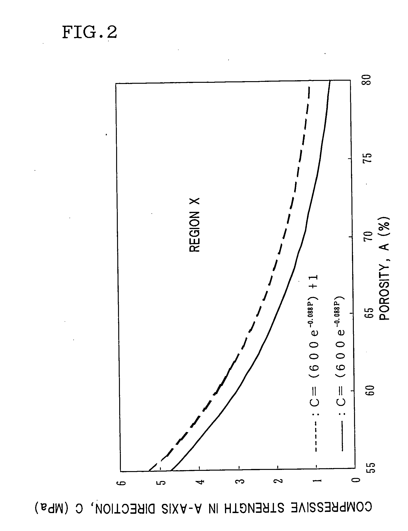
The present invention provides a honeycomb structure that is resistant to damage even with high porosity or open frontal area. The structure has a relation of Z1=0.5, preferably Z1=1.0, and more preferably Z1=1.5 in the formula below: C≧(600e−0.0AP)+Z1 The structure also has a thermal expansion coefficient of partition walls in B-axis direction of ≤10×10−6 / °C. The structure can be used as an exhaust gas purification filter or a catalyst carrier. The method for producing the structure involves a forming step and a firing step. The structure has a pore volume ratio of pores with pore diameters of 10 to 40 μm to all pores of ≥50%. The pore-forming material can contain a resin that foams by heating or a foamed resin. The honeycomb structure is suitable for use as an exhaust gas purification filter or a catalyst carrier.

Problems solved by technology

On the other hand, when a honeycomb structure is used as a DPF, a catalyst carrier, or the like, pressure loss of exhaust gas becomes a problem.
That is, pressure loss of exhaust gas is caused because exhaust gas passes through a honeycomb structure, which leads to decrease in output or increase in fuel consumption of an internal combustion engine such as a diesel engine or a gasoline engine.
However, raising porosity or open frontal area of a honeycomb structure generally causes deterioration in isostatic strength of the honeycomb structure, and the honeycomb structure is prone to be damaged.
However, there has not been obtained a honeycomb structure which has small pressure loss and which is hardly damaged.

Method used


Image

  • Honeycomb structure
  • Honeycomb structure
  • Honeycomb structure

Examples


examples

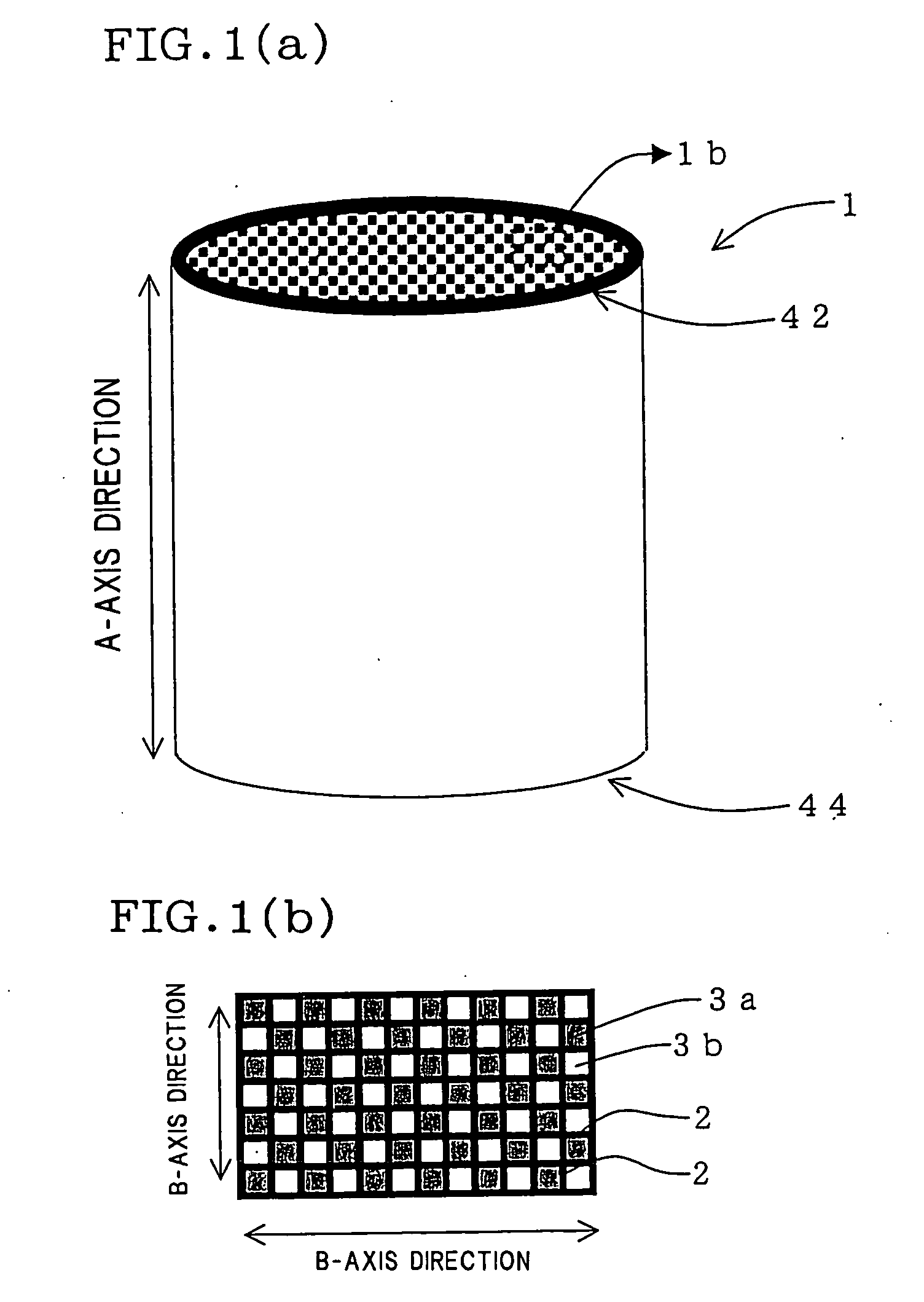
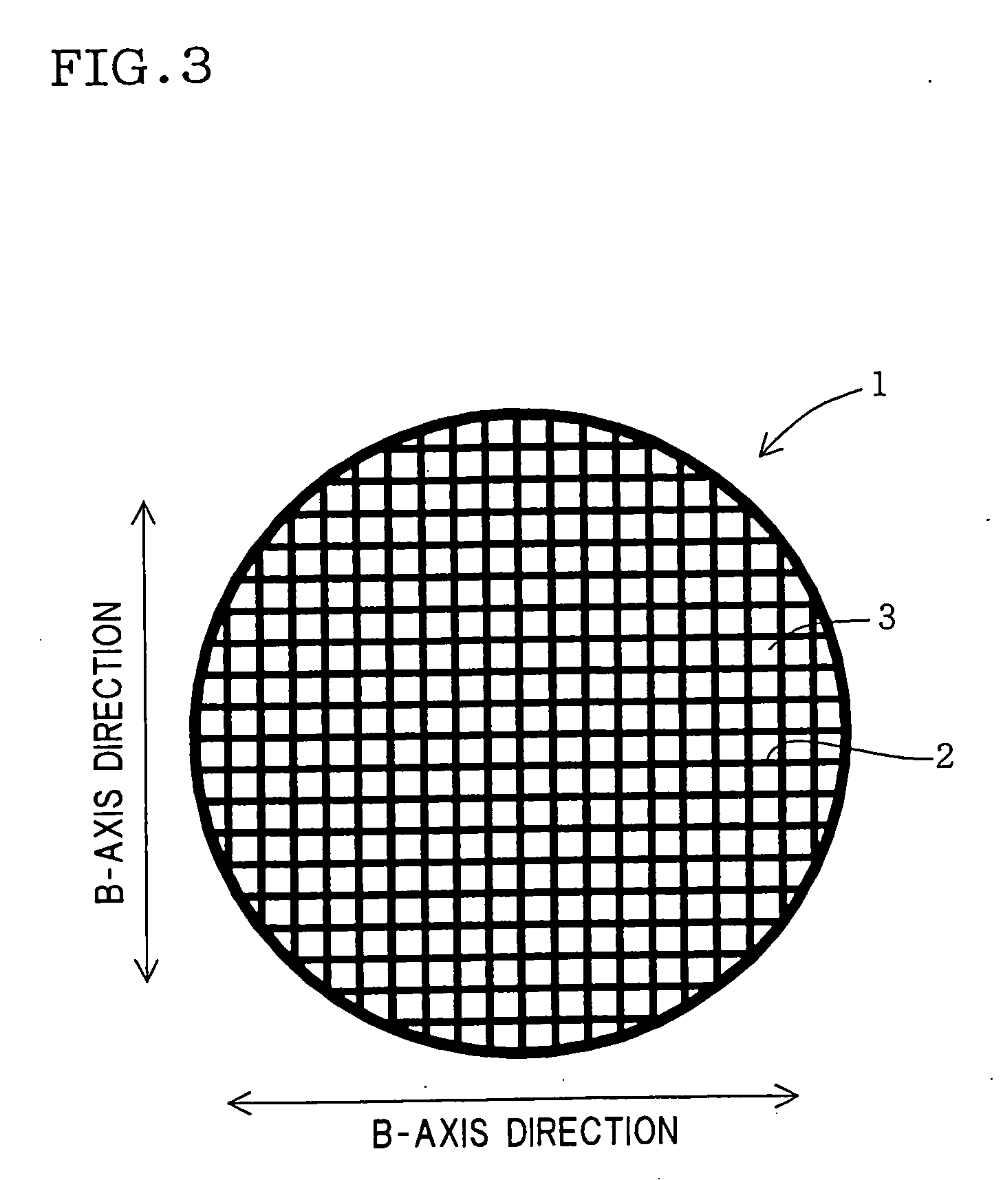
[0023] A honeycomb structure as the first aspect of the present invention and a production method thereof and a method for producing a honeycomb structure as the second aspect of the present invention and a honeycomb structure obtained by the method will hereinbelow be described in detail on the basis of specific embodiments. However, the present invention is by no means limited to the following embodiments. Incidentally, a “cross section” means a section perpendicular to a longitudinal direction (e.g., A-axis direction in FIG. 1(a)) of through holes as long as a particular comment is not made.

[0024] A honeycomb structure 1 of the first aspect of the present invention contains cordierite as the main component and is provided with porous partition walls 2 disposed so as to form a plurality of through holes 3a and 3b extending from one end portion (end portion 42) to the other end portion (end portion 44) in A-axis direction.

[0025] The important characteristic of the first aspect of...


PUM

PropertyMeasurementUnit
pore diameteraaaaaaaaaa
pore diametersaaaaaaaaaa

Abstract

There is provided a honeycomb structure 1 including porous partition walls 2 disposed so as to form a plurality of through holes 3a, 3b extending from one end portion to the other end portion in A-axis direction, and containing cordierite as a main component. When porosity is P (%), compressive strength in the A-axis direction is C(MPa), and open frontal area is A (%); a relation of C≧(600e−0.0014AP)+0.5 is satisfied. The honeycomb structure has small pressure loss, is hardly damaged, and has excellent trapping efficiency.

Description

TECHNICAL FIELD [0001] The present invention relates to a honeycomb structure. Particularly, the present invention relates to a honeycomb structure which can suitably be employed as a filter for purifying exhaust gas or as a catalyst carrier. BACKGROUND OF THE INVENTION [0002] There has recently been highlightened on a large scale an influence of particulate matter emitted from a diesel engine or the like or NOx upon environment. As an important means to remove such harmful matter, various studies are made with regard to usage of a honeycomb structure having porous partition walls as a filter, catalyst carrier, or the like. [0003] For example, there has been developed a honeycomb structure for a filter for trapping particulate matter (hereinbelow referred to as PM) emitted from a diesel engine (the filter is hereinbelow referred to as DPF). A honeycomb structure for a DPF generally has porous partition walls disposed so as to form a plurality of through holes extending in an axial d...

Claims


Application Information

Patent Timeline
Patent Type & Authority Applications(United States)
IPC IPC(8): B01D50/00B01D39/00F01N3/02B01D39/20B01D46/00B01D46/24B01D53/86B01D53/94B01J21/16B01J32/00B01J35/00B01J35/04B01J35/10C04B38/00F01N3/022F01N3/28
CPCB01D46/2425Y10S55/10B01D46/2444B01D46/2466B01D46/247B01D46/2474B01D53/86B01D53/94B01D2046/2433B01D2046/2437B01D2046/2496B01D2275/30B01J35/002B01J35/04B01J35/10C04B38/0006F01N3/0222B01D46/2429Y10S55/30Y02T10/20Y10T428/24149Y10S55/05Y10S264/48C04B35/195Y02T10/12B01D46/24492B01D46/24491B01D46/2498B01D46/2484B01D46/2482B01D46/24494B01J35/56B01J35/60B01J35/40B01J35/66
Inventor SUZUKI, KYOKOMATSUMOTO, KEIJISUENOBU, HIROYUKI
Owner NGK INSULATORS LTD
Learn More