
Efficient clock models and their use in simulation

a clock model and simulation technology, applied in the field of simulation models, can solve the problems of only affecting the overall performance of the system-level model, and achieve the effects of greater simulation accuracy, faster execution, and higher accuracy

Active Publication Date: 2006-08-31
SYNOPSYS INC
View PDF20 Cites 3 Cited by
  • Summary
  • Abstract
  • Description
  • Claims
  • Application Information

AI Technical Summary

Benefits of technology

[0010] Accordingly, a method and / or system for improving the performance of system-level simulation models would be advantageous. In particular, a simulation that can be performed more quickly and with more accuracy than conventionally possible would be advantageous. Embodiments in accordance with the present invention provide this and other advantages.
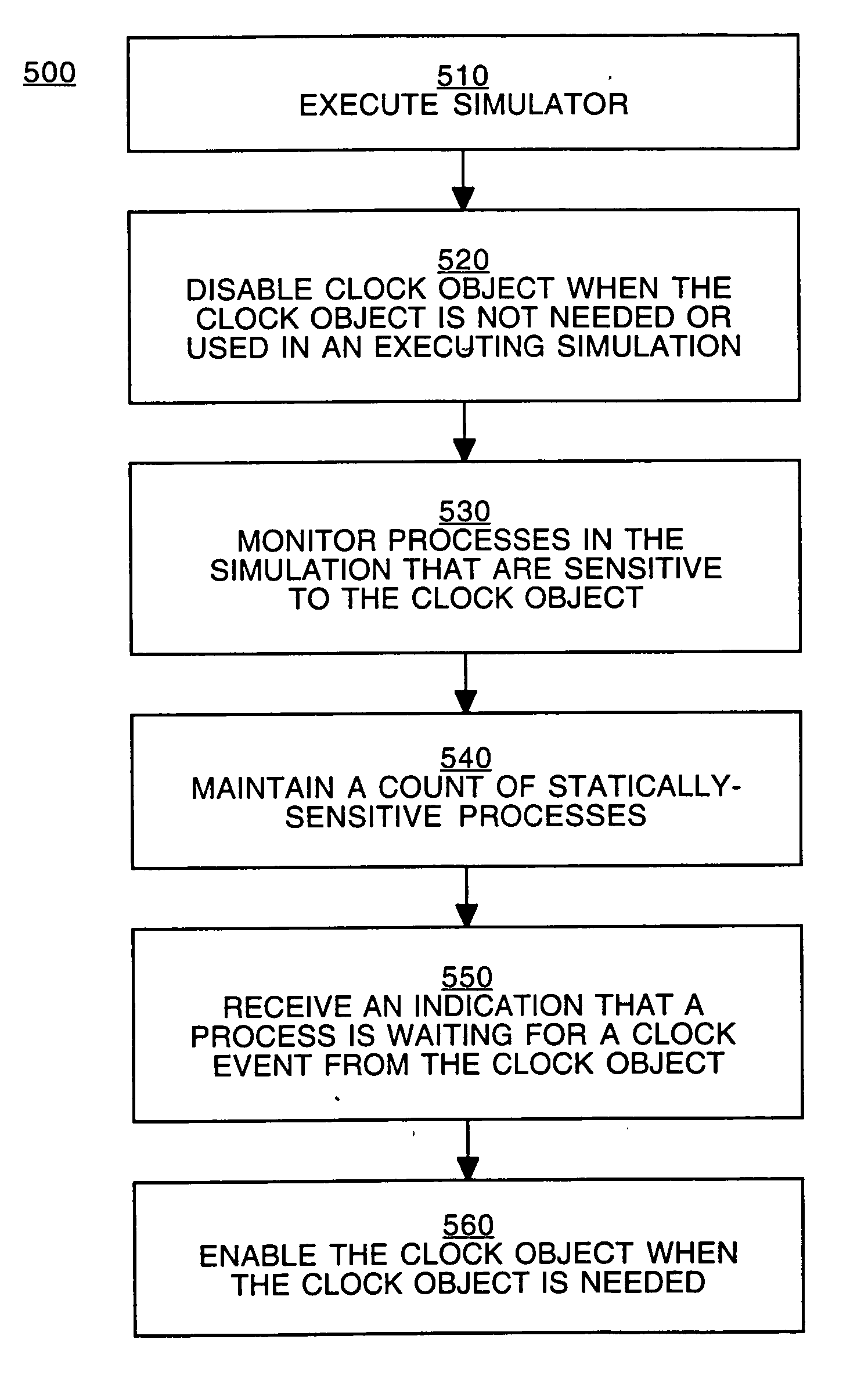
[0012] According to embodiments of the present invention, a first device model in a system of devices can be simulated using time steps of one length (e.g., larger time steps), and a second device model in that system can be simulated using time steps of another (e.g., shorter) length. The second device model may be used to simulate a new hardware device, or to simulate execution of a new software application on a particular device—generally speaking, the second device model is used when greater simulation accuracy is desired for a particular device in a system of devices. During times that the second device model is active during simulation, the system-level model executes using shorter time steps, but during times that the second device model is not active during simulation, the clock object for the second device model is disabled and the system-level model executes using larger time steps. Thus, higher accuracy can be achieved using the second device model, but overall performance of the system-level model is only affected when the second device model is active. Thus, the simulation model can be executed more quickly and with greater accuracy than conventional models.
[0013] There are other advantages associated with embodiments in accordance with the present invention. For example, the design of timer models is facilitated, and modeling with the present invention clock objects is a modeling style readily adoptable by designers. These and other objects and advantages of the present invention will be recognized by one skilled in the art after having read the following detailed description, which are illustrated in the various drawing figures.

Problems solved by technology

Thus, higher accuracy can be achieved using the second device model, but overall performance of the system-level model is only affected when the second device model is active.

Method used


Image

  • Efficient clock models and their use in simulation
  • Efficient clock models and their use in simulation
  • Efficient clock models and their use in simulation

Examples


Embodiment Construction

[0020] In the following detailed description of the present invention, numerous specific details are set forth in order to provide a thorough understanding of the present invention. However, it will be recognized by one skilled in the art that the present invention may be practiced without these specific details or with equivalents thereof. In other instances, well-known methods, procedures, components, and circuits have not been described in detail as not to unnecessarily obscure aspects of the present invention.

[0021] Some portions of the detailed descriptions, which follow, are presented in terms of procedures, steps, logic blocks, processing, and other symbolic representations of operations on data bits that can be performed on computer memory. These descriptions and representations are the means used by those skilled in the data processing arts to most effectively convey the substance of their work to others skilled in the art. A procedure, computer executed step, logic block,...


PUM


Abstract

Methods simulating a system of devices are described. A model that simulates the system is executed. The system model includes a plurality of modules. A clock object for a module can be disabled when it is not needed or not being used.

Description

BACKGROUND OF THE INVENTION [0001] 1. Field of the Invention [0002] Embodiments in accordance with the present invention generally pertain to electronic design automation. In particular, embodiments in accordance with the present invention pertain to simulation models used for system-level modeling. [0003] 2. Related Art [0004] A system on a chip (SOC) may be relatively large and complex, incorporating multiple processors as well as other devices that support display, memory and keypad capabilities. System-level models are used to simulate systems such as SOCs during the design process (e.g., before they are implemented in hardware). Using system-level simulation, software that will run on systems such as SOCs can be designed and tested in parallel with the hardware design. [0005] The computational complexity of system-level simulation models means that the simulation runs slower relative to the speed of execution of an actual hardware platform. Increasing the speed of simulation is...

Claims


Application Information

Patent Timeline
IPC IPC(8): G06F17/50
CPCG06F17/5022G06F30/33
Inventor VERMEERSCH, DIRKROMPAY, KARL VAN
Owner SYNOPSYS INC
Learn More