Method for making a magnetoresistive read head having a pinned layer width greater than the free layer stripe height

Inactive Publication Date: 2006-09-07
HITACHI GLOBAL STORAGE TECH NETHERLANDS BV
View PDF15 Cites 12 Cited by
  • Summary
  • Abstract
  • Description
  • Claims
  • Application Information

AI Technical Summary

Benefits of technology

[0011] The invention is a method for making a magnetoresistive read head wherein the pinned layer has a width greater than the stripe height of the free layer. The read head stack of layers on the substrate is patterned with photoresist. The pattern has a rectangular region with front and back long edges. The substrate is located on an adjustable and rotatable platform in a conventional ion beam etching tool and the platform is aligned at an angle to the ion beam and oriented such that the back long edge of the photoresist pattern is orthogonal to the in-plane directional component of the ion beam. The stack of layers is then ion milled down to the spacer layer so that at least a portion of the spacer layer and all the layers in the stack above it are removed in the areas exposed to the incident ions. However, because a section of the stack in the front of the front long edge is protected from the ion beam due to the angle of the ion beam and the thickness of the photoresist, this section retains the spacer layer and the layers above it. After this initial ion milling phase the platform is rotated approximately 180 degrees so that the front long edge is oriented orthogonal to the in-plane directional component of the ion beam. The stack is then ion milled down to the substrate, which is typically an insulating gap layer if the read head is a CIP-SV read head. This second ion milling phase removes the pinned layer and the layers in the stack below it in the areas exposed to the incident ions. Because a section of the stack behind the back long edge is protected from the ion beam due to the angle of the ion beam and the thickness of the photoresist, this section retains the spacer layer and the layers above it. Thus after the subsequent lapping, this section behind the back long edge creates an extension to the pinned layer so that the width of the pinned layer is greater than the stripe height of the free layer by the width of the extension. The pinned layer extension makes the volume of magnetic material in the pinned layer greater than it would be if its width were equal to the stripe height. Thus the method of this invention enables the free layer dimensions to be made smaller without causing magnetic instability in the pinned layer.

Problems solved by technology

As previously described, because this process patterns the free and pinned layers simultaneously to the same dimensions, it is not possible to reduce the dimensions of the free layer without also reducing the dimensions of the pinned layer, thereby making the pinned layer more susceptible to magnetic instability.

Method used


Image

  • Method for making a magnetoresistive read head having a pinned layer width greater than the free layer stripe height
  • Method for making a magnetoresistive read head having a pinned layer width greater than the free layer stripe height
  • Method for making a magnetoresistive read head having a pinned layer width greater than the free layer stripe height

Examples


Embodiment Construction

Prior Art

[0024] Because this invention relates to the manufacture of magnetoresistive read heads which are used in magnetic recording disk drives, the operation of a conventional disk drive will be briefly described with reference to FIGS. 1-3.

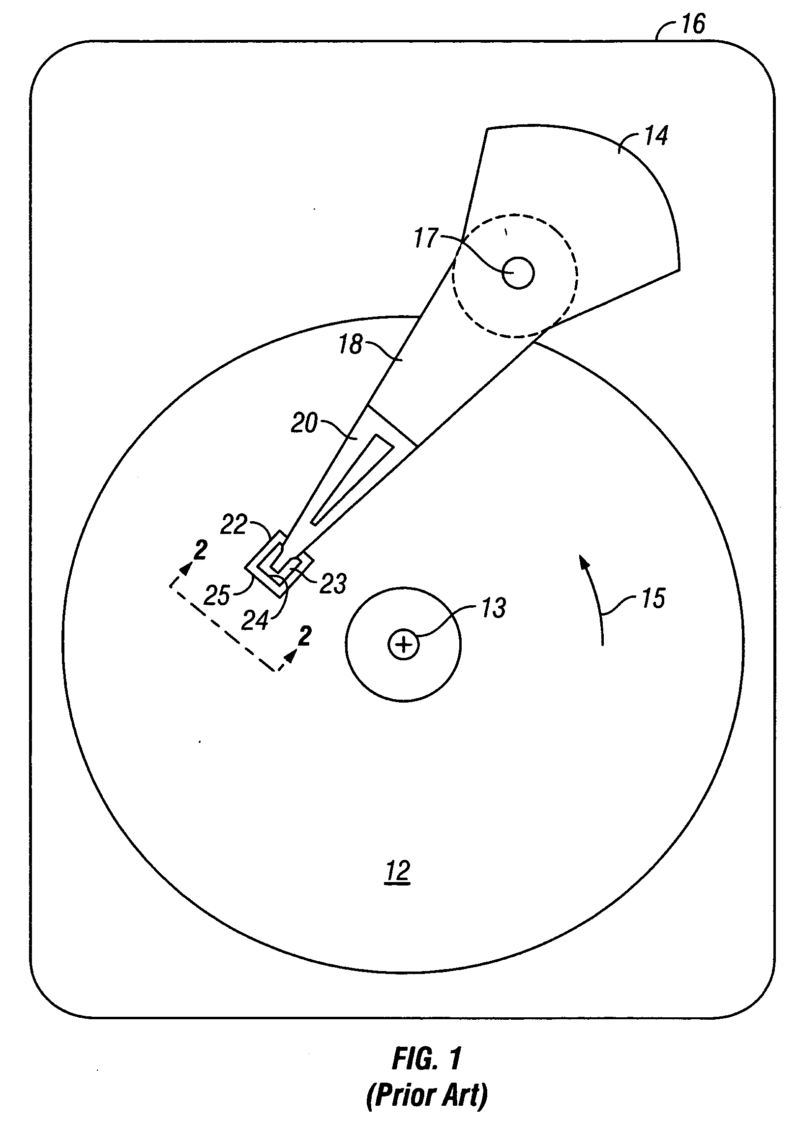
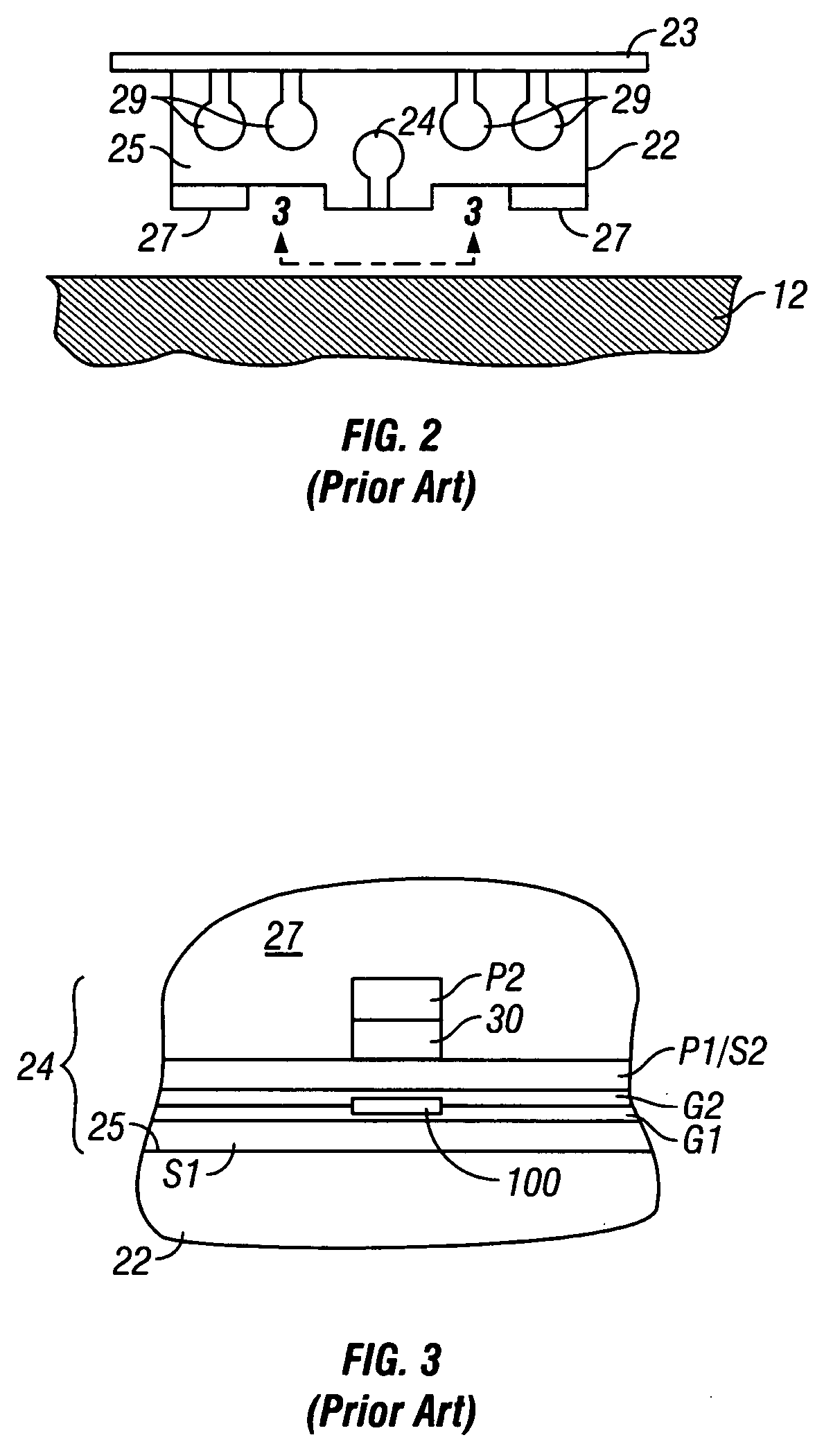
[0025]FIG. 1 is a block diagram of a conventional magnetic recording hard disk drive. The disk drive includes a magnetic recording disk 12 and a rotary voice coil motor (VCM) actuator 14 supported on a disk drive housing or base 16. The disk 12 has a center of rotation 13 and is rotated in direction 15 by a spindle motor (not shown) mounted to base 16. The actuator 14 pivots about axis 17 and includes a rigid actuator arm 18. A generally flexible suspension 20 includes a flexure element 23 and is attached to the end of arm 18. A head carrier or air-bearing slider 22 is attached to the flexure 23. A magnetic recording read / write head 24 is formed on the trailing surface 25 of slider 22. The flexure 23 and suspension 20 enable the slider to “...


PUM

PropertyMeasurementUnit
Thicknessaaaaaaaaaa
Antiferromagnetismaaaaaaaaaa
Electrical conductoraaaaaaaaaa

Abstract

A method for making a magnetoresistive read head so that the pinned ferromagnetic layer is wider than the stripe height of the free ferromagnetic layer uses ion milling with the ion beam aligned at an angle to the substrate supporting the stack of layers making up the read head. The stack is patterned with photoresist to define a rectangular region with front and back long edges aligned parallel to the read head track width. After ion milling in two opposite directions orthogonal to the front and back long edges, the pinned layer width has an extension. The extension makes the width of the pinned layer greater than the stripe height of the free layer after the substrate and stack of layers are lapped. The length of the extension is determined by the angle between the substrate and the ion beam and the thickness of the photoresist.

Description

BACKGROUND OF THE INVENTION [0001] 1. Field of the Invention [0002] The invention relates generally to magnetoresistive sensors or read heads for reading magnetically recorded data, and more particularly to a method for making such heads. [0003] 2. Description of the Related Art [0004] In magnetic recording disk drives the conventional sensor for reading the data recorded on the magnetic medium is a magnetoresistive “spin-valve” (SV) read head. The SV read head is a stack of layers that includes two ferromagnetic layers separated by a nonmagnetic electrically-conductive spacer layer. One ferromagnetic layer, typically the bottom ferromagnetic layer closer to the read head substrate, has its magnetization direction fixed or pinned, typically by being exchange coupled with an underlying antiferromagnetic layer. The other ferromagnetic layer is the “sensing” layer that has its magnetization direction “free” to rotate in the presence of the external magnetic field from the recorded data...

Claims


Application Information

Patent Timeline
IPC IPC(8): G11B5/127C23C14/00
CPCB82Y10/00B82Y25/00G01R33/093G11B5/3163G11B5/3169Y10T29/49052G11B2005/3996Y10T29/49041Y10T29/49044Y10T29/49048Y10T29/49046G11B5/3903
Inventor CYRILLE, MARIE-CLAIREDING, MENGDOBISZ, ELIZABETH ANNHO, KUOK SANMACDONALD, SCOTT ARTHUR
Owner HITACHI GLOBAL STORAGE TECH NETHERLANDS BV
Why Eureka
Try Eureka