Anvil with vacuum width adjustment

Inactive Publication Date: 2006-09-07
THE GOODYEAR TIRE & RUBBER CO
View PDF18 Cites 53 Cited by
  • Summary
  • Abstract
  • Description
  • Claims
  • Application Information

AI Technical Summary

Benefits of technology

[0025]FIG. 1 is a schematic view of a multi-layer elastomeric composite strip, showing the location of the cut to be made;
[0026]FIG. 2 is a top view of the multi-layer elastomeric composite of FIG. 1 cut to the desired length;
[0027]FIG. 3 is a cross sectional view i

Problems solved by technology

If the laminate structure includes a reinforcement layer such as reinforced ply containing closely spaced reinforcement cords, it is an engineering challenge to be able to cut through the laminate structure to the desired leng

Method used


Image

  • Anvil with vacuum width adjustment
  • Anvil with vacuum width adjustment
  • Anvil with vacuum width adjustment

Examples


Embodiment Construction

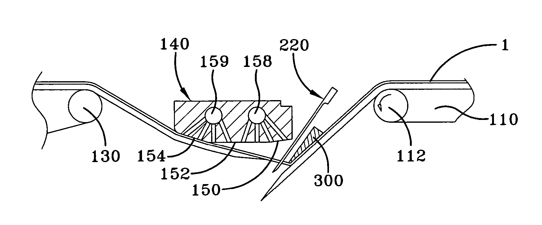
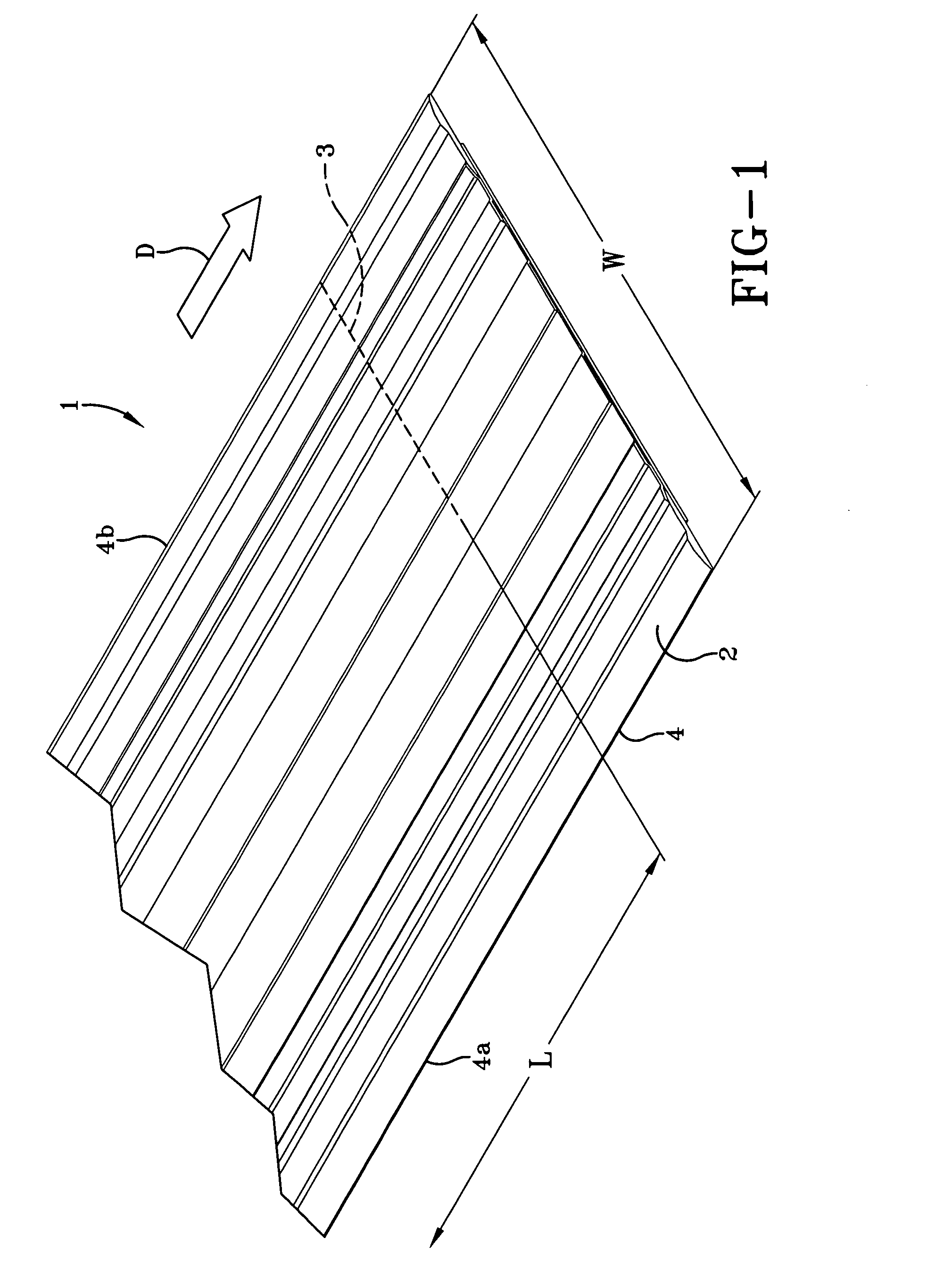
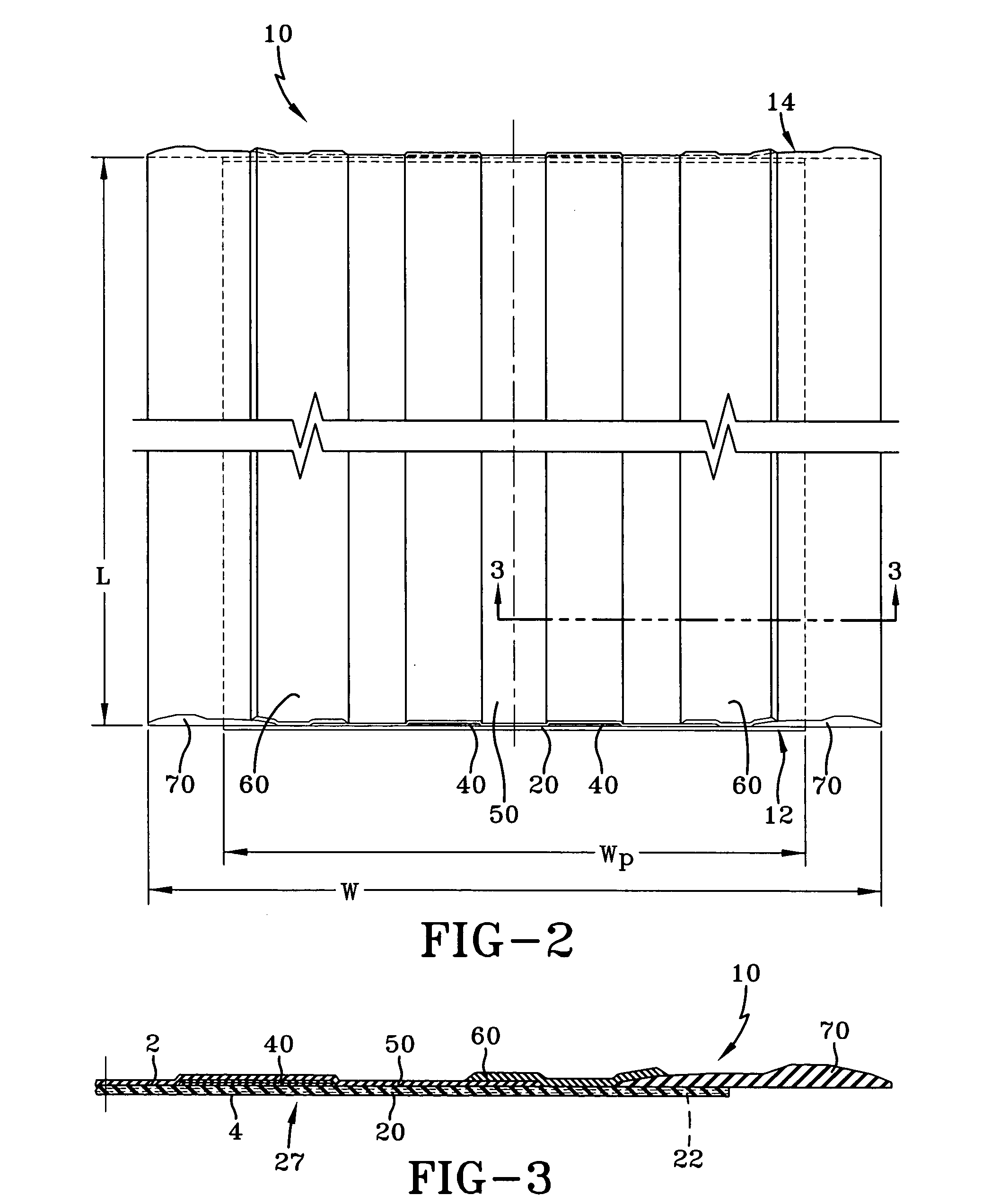
[0047] A strip of elastomeric composite or laminate structure 1 to be cut by the method and apparatus of the invention is shown in FIGS. 1-3. However, the cutting apparati described herein are not limited to cutting laminate, as other materials such as ply or gum components may be used. The laminate 1 has a width W and an indefinite length designated by the L direction. The dotted line 3 shows the location or path of a lateral cut that is to be made across the width of the laminate 1. The path 3 can be perpendicular to the length L of the laminate or at an oblique angle across the width W. If the laminate 1 has one or more reinforcement layers of parallel cords 22 that are similarly oriented, then it is preferred that the cutting path 3 be oriented relative to the cord 22 path.

[0048] In the various figures shown, the laminate 1 may include various components used in the manufacture of tires. FIGS. 2 and 3 illustrate one example of a laminate 1 having an optional ply layer 20 compri...


PUM

PropertyMeasurementUnit
Lengthaaaaaaaaaa
Angleaaaaaaaaaa
Widthaaaaaaaaaa

Abstract

A method and apparatus is provided for cutting an elastomeric laminate that may include a layer of reinforcement cords, into a desired length without cutting through the cords. The method includes the step of cutting through the gum portion of the elastomeric composite material at a desired skive angle, and then opening up the skived cut. Next, the cord reinforcement layer is cut without severing the reinforcement cords. An elastomeric composite strip cut to the desired length is produced and has cut ends. One of the cut ends has the gum portion cut at a desired skive angle adjacent an overhang portion of the reinforcement layer. The opposite end of the elastomeric composite segment also has a skived portion to mate with the skived portion of the first cut end, and a gap in the cord ply to mate with the cord overhang of the first end, resulting in a splice. An improved anvil having independently controlled vacuum zones and adjustable width vacuum zones is also provided, as well as improved cutting mechanisms.

Description

[0001] This application claims the benefit of U.S. provisional application No. 60 / 638,688, filed Dec. 23, 2004.TECHNICAL FIELD [0002] This invention relates to methods and apparati for cutting elastomeric materials at low skive angles, and cutting a multilayered elastomeric composite including one or more layers containing reinforcing materials. BACKGROUND OF THE INVENTION [0003] Historically, the pneumatic tire has been fabricated as a laminate structure of generally toroidal shape having beads, a tread, belt reinforcement and a carcass. The manufacturing technologies employed for the most part involve the successive assembling of multiple tire components onto a tire building drum wherein each tire component is cut to length and spliced on the drum. A typical tire may comprise about six splices spaced about the tire. [0004] Recent advances in the first stage of tire subassembly construction involve the utilization of a single unvulcanized laminated structure, such as described in U...

Claims


Application Information

Patent Timeline
IPC IPC(8): B26D7/06
CPCB26D1/04B26D3/003B26D3/08B26D7/018B26D7/0625B26D7/086B26D11/00B26D2001/0026Y10T83/207Y10T83/2185Y10T83/364Y10T83/768Y10T83/9309
Inventor DOWNING, DANIEL RAYDEJACIMO, DAVID MICHAELLUNDELL, DENNIS ALANKITZ, STEVEN LEONARDTHOMPSON, MARK ALAN
Owner THE GOODYEAR TIRE & RUBBER CO
Why Eureka
Try Eureka