
Dielectric elastomer composites and actuators using the same

a technology of dielectric elastomer and composite actuator, which is applied in the direction of electrical equipment, electromechanical/electrostrictive/magnetostrictive devices, coatings, etc., can solve the problems of low mechanical strain, high brittleness and high manufacturing cost, and high operating voltage, so as to improve the dispersibility of fillers, improve the electromechanical properties of polymer composite actuators, and improve the effect of filler dispersibility

Inactive Publication Date: 2013-02-28
KOREA INST OF SCI & TECH
View PDF5 Cites 23 Cited by
  • Summary
  • Abstract
  • Description
  • Claims
  • Application Information

AI Technical Summary

Benefits of technology

The present invention describes a way to improve the electromechanical properties of a polymer composite actuator by adding a compound with an amine end group or a pyrene derivative as a dispersing agent. This helps to better mix the fillers in the polymer matrix, which leads to a higher dielectric constant and better performance of the actuator. By using specific polymers as the matrix, such as elastomers with maleic anhydride, acrylic, urethane, carboxylic, or amine groups, the actuator's mechanics can be greatly enhanced.

Problems solved by technology

Conventional devices (electromechanical devices) that convert electrical energy into mechanical energy and capable of being used in robotics, pumps, speakers, disc drives, camera lenses, etc. have used piezoelectric ceramic materials, but have disadvantages such as low mechanical strain, high brittleness and high manufacturing cost.
Actuators using resilient dielectric layers as above have advantages such as having a very high speed of converting electrical energy into mechanical energy and high strain value, but are problematic in that their operating voltage is very high.
In the above-mentioned conventional techniques, however, there are limitations in enhancing the electromechanical conversion efficiency, because the dispersed phase of the fillers is formed in a dispersed phase size of micrometer level while the formation of the aggregates of fillers leads to the formation of conduction pass, resulting in di-electric loss.
Thus, there was a disadvantage in that, when fillers were added, the di-electric loss and leakage current increased and the breakdown strength became poor (see U.S. Pat. No. 6,909,220 and PCT International Patent Publication No.

Method used


Image

  • Dielectric elastomer composites and actuators using the same
  • Dielectric elastomer composites and actuators using the same
  • Dielectric elastomer composites and actuators using the same

Examples


example 1

[0046]Styrene-ethylbutylene-styrene-g-maleic anhydride (SEBS-g-MA) copolymer (Trade

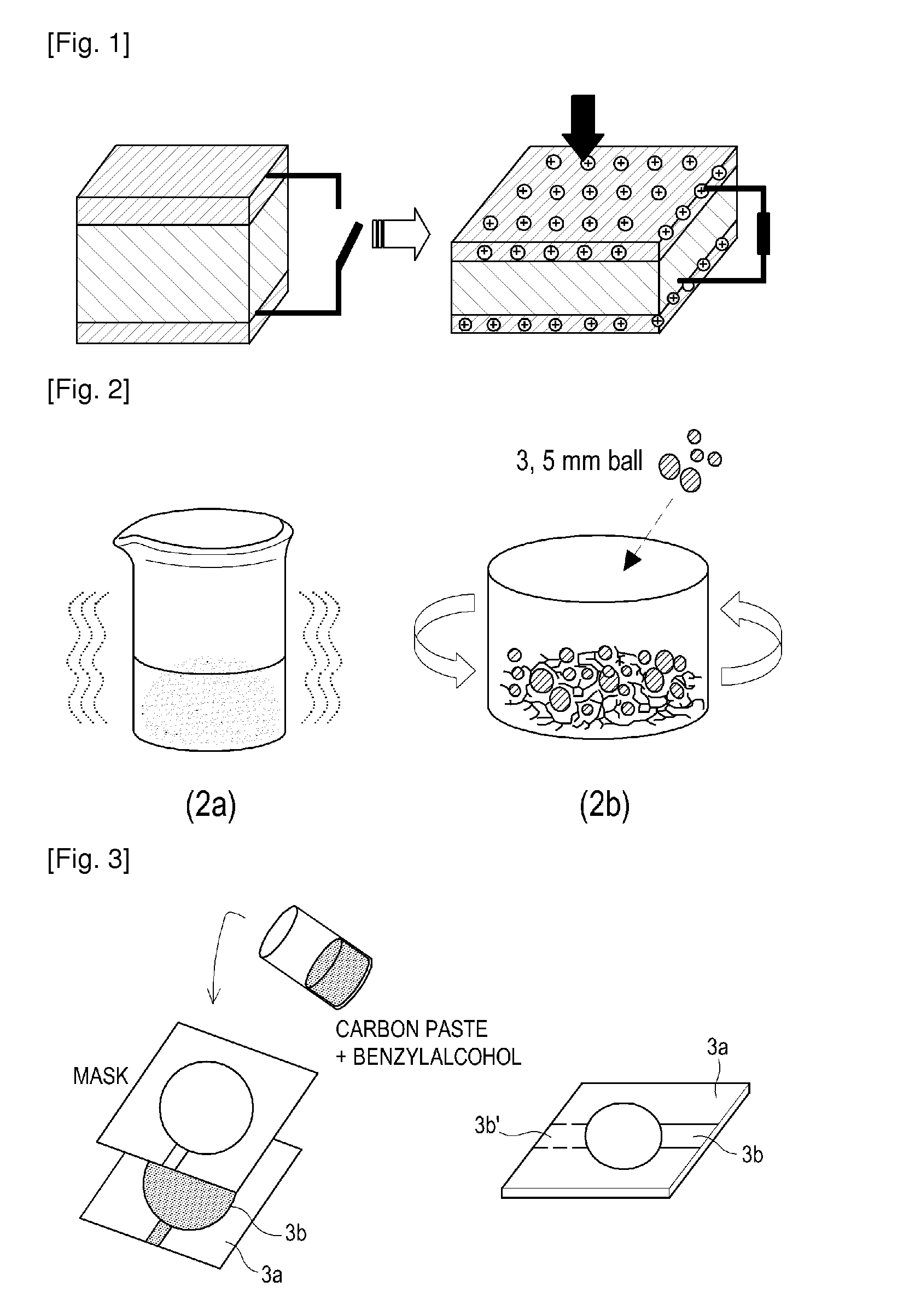
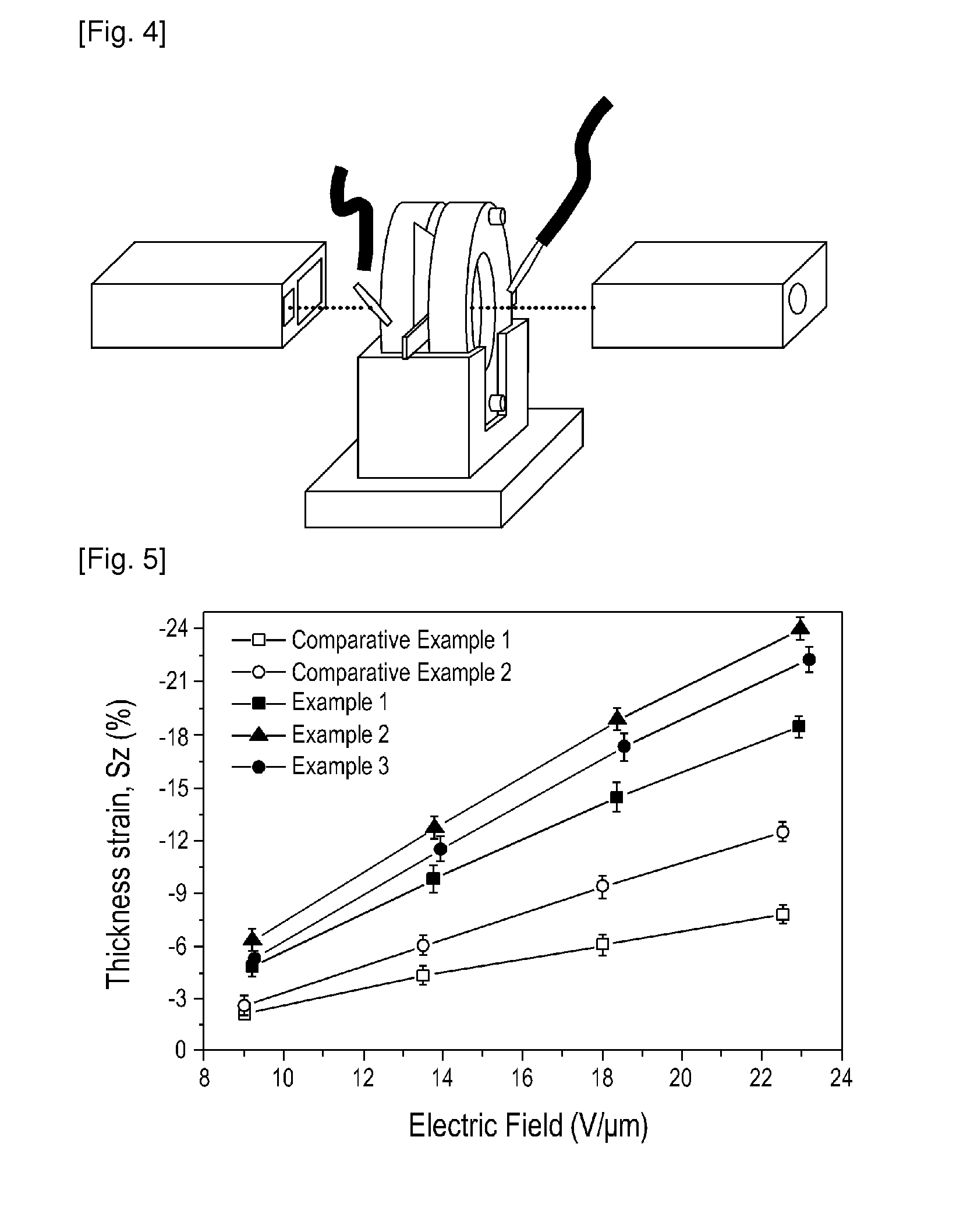
[0047]Name: FG1901X) having a polar group and provided by Kraton Polymers LLC was used as the resilient dielectric layer (3a). In order to impart plasticization, paraffin-based oil (T-150) purchased from Michang Oil Industry Co. LTD, was added thereto. The copolymer and oil were combined at a content ratio of 20 weight %: 80 weight %. Based on the matrix content, 0.05 weight % of the fillers, single-walled carbon nanotubes (SWCNT, AST-100F) provided by Hanwha Nanotech Co., were subjected to sufficient sonication (2a) with the addition of toluene. Thereafter, ball-milling using a zirconium ball (2b) was performed in a slurry state at 400 rpm for 3 hours. In order to prepare a sample as shown in FIG. 3a, a 7-ton force was applied thereto at 100° C. by compression molding to obtain a resilient dielectric layer of 60×60×0.5 mm3. When forming the upper electrode plane (3b) and the lower electrode plane (3b...

example 2

[0048]In the resilient insulating elastomer matrix, the weight ratio of styrene-ethylenebutylene-styrene comprising maleic anhydride (SEBS-g-MA) to the oil was fixed to 20 weight %: 80 weight %, as described in Example 2. As shown in FIG. 2a, based on the matrix content, 0.05 weight % of the fillers, single-walled carbon nanotubes (SWCNT, AST-100F) provided by Hanwha Nanotech Co., were added thereto and subjected to ultrasonic treatment for a sufficient time with the addition of toluene and 0.1 weight % of the pyrene derivative, N-hexadecylpyrene-1-sulfonamide (Aldrich), which is a dispersion agent. As shown in FIG. 2b, the above mixture was well sonicated with SEBS-g-MA copolymer swelled in paraffin-based oil in a bowl, followed by ball-milling using a zirconium ball in a slurry state for 3 hours with the addition of fillers comprising N-hexadecylpyrene-1-sulfonamide.

[0049]The processes for forming a resilient dielectric layer (3a) and upper / lower electrodes (3b) were carried out a...

example 3

[0050]A resilient insulating elastomer matrix (FIG. 3a) as described in Example 1 was used. 30 weight % of copper phthalocyanine (CuPc) was added thereto as a filler to prepare a dielectric elastomer composite. In order to facilitate the dispersion of the fillers, ultrasonic treatment was performed with the addition of 0.1 weight % of polystyrene having an amine end group which is a dispersing agent for improving the dispersibility of the fillers. SEBS-g-MA, paraffin-based oil, and CuPc comprising polystyrene that has an amine end group were added to the bowl, and toluene was used as a solvent. A zirconium ball was put into the bowl where ball-milling was performed for 3 hours while maintaining the speed at 400 rpm. After the ball-milling was finished, the processes for forming a resilient dielectric layer (3a) and upper / lower electrodes (3b) were carried out as described in Example 1.


PUM


Abstract

The present invention relates to an actuator which is one of the energy conversion devices, and is characterized by improving the ability to convert electrical energy into mechanical energy by way of using a dielectric elastomer composite comprising a filler with an efficient dispersibility. In case of using a conventional resilient dielectric layer, there was a problem in that the operating voltage is high, while advantageously exhibiting a fast response and a high strain. The present invention can provide dielectric elastomer composite actuators that show excellent electromechanical conversion properties, by adding a dispersing agent such as a pyrene derivative or a polymeric compound having an amine end group when preparing the composite wherein carbon-based conductive fillers such as carbon blacks, single-walled carbon nanotubes (SWCNTs), double-walled carbon nanotubes (DWCNTs), multi-walled carbon nanotubes (MWCNTs) and graphenes, or high dielectric fillers such as copper phthalo-cyanine (CuPc), MOFs (metal organic frameworks) and barium titanate (BaTiO3) are comprised in a thermoplastic resilient dielectric layer to enhance the dispersibility of the fillers.

Description

TECHNICAL FIELD[0001]The present invention generally relates to dielectric elastomer composite actuators that convert electrical energy into mechanical energy, and more particularly to polymer composite actuators with enhanced electromechanical convertibility of the dielectric elastomer composites by including fillers having an effective dispersibility.BACKGROUND ART[0002]Conventional devices (electromechanical devices) that convert electrical energy into mechanical energy and capable of being used in robotics, pumps, speakers, disc drives, camera lenses, etc. have used piezoelectric ceramic materials, but have disadvantages such as low mechanical strain, high brittleness and high manufacturing cost. In order to overcome such drawbacks, there have been a great deal of research on technologies that can substitute the above piezoelectric ceramic materials with polymers. Recently, actuators using elastomers with dielectric properties like acrylic rubber, silicone rubber, acrylonitrilbu...

Claims


Application Information

Patent Timeline
IPC IPC(8): H02N11/00B05D5/12B82Y99/00H01L41/45
CPCH01L41/0986H01L41/45H01L41/193H10N30/206H10N30/857H10N30/098
Inventor KOO, CHONG MINHONG, SOON MANHWANG, SEUNG SANGBAEK, KYUNG YOULKWAK, SOON JONGKIM, MYUNG HEEKIM, BO RIKWAK, HEE LAMIN, KYUNG HOPARK, YOUN DUK
Owner KOREA INST OF SCI & TECH
Learn More