Method and device for controlling an internal combustion engine

a technology of internal combustion engine and control device, which is applied in the direction of electric control, machines/engines, output power, etc., can solve the problems of low frictional loss, achieve small risk of misfiring, improve mixture preparation, and increase valve lift

Active Publication Date: 2006-09-07
VITESCO TECH GERMANY GMBH
View PDF7 Cites 5 Cited by
  • Summary
  • Abstract
  • Description
  • Claims
  • Application Information

AI Technical Summary

Benefits of technology

[0006] The object of the invention is to create a method and a device for controlling an internal combustion engine which ensures that low emissions of noxious substances are generated.

Problems solved by technology

This results in lower frictional losses based on the small diameter of the cam and the cylinder element used in this mode of operation and the lower valve lift.

Method used


Image

  • Method and device for controlling an internal combustion engine
  • Method and device for controlling an internal combustion engine
  • Method and device for controlling an internal combustion engine

Examples


Embodiment Construction

[0023] Elements with the same design and function are characterized in all the figures with the same reference symbols.

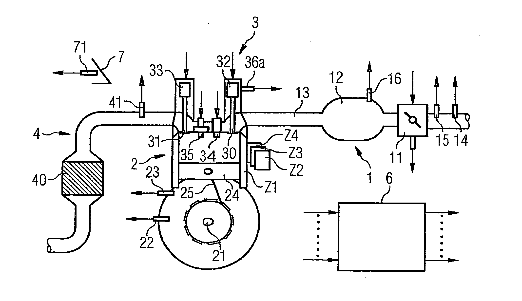
[0024] An internal combustion engine (FIG. 1) includes an intake tract 1, an engine block 2, a cylinder head 3 and an exhaust gas tract 4. The intake tract preferably includes a throttle valve 11, a manifold 12 and an intake pipe 13, which is guided to a cylinder Z1 via an intake port in the engine block. The engine block also includes a crankshaft 21, which is connected to the piston 24 of a cylinder Z1 by means of a connecting rod 25.

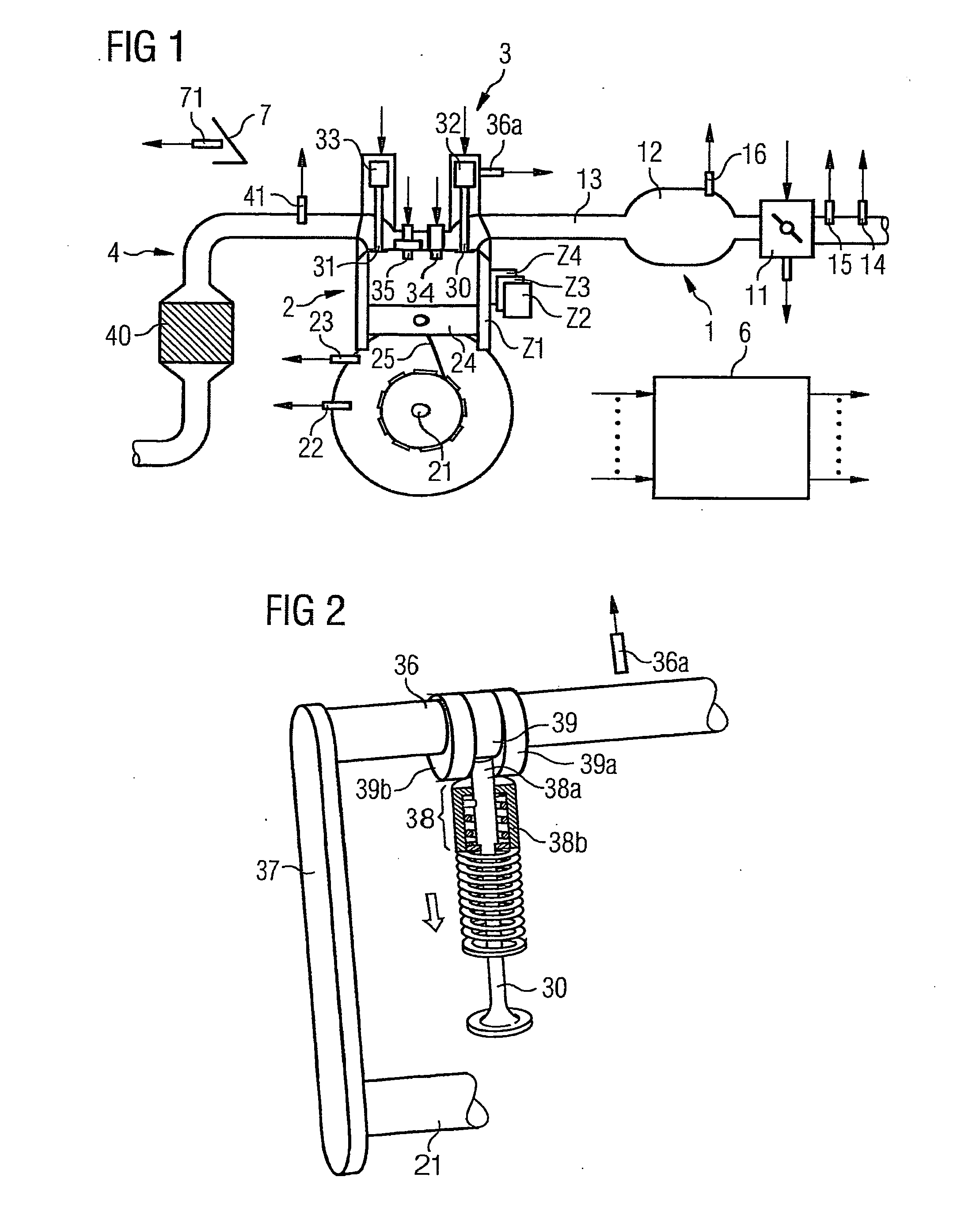
[0025] The cylinder head includes a drive with an intake valve 30, an exhaust valve 31 and valve gears 32, 33. The gas intake valve 30 and the gas exhaust valve 31 are driven by means of a camshaft 36 (see FIG. 2) on which cams 39, 39a and 39b are embodied for driving the gas intake valve 30. In addition, cams which are not shown are provided on an additional camshaft which drive the gas intake valve 31.

[0026] A total of three cams...


PUM


Abstract

The invention relates to a method and device for controlling an internal combustion engine comprising an inlet pipe leading to a cylinder input where a gas input valve is placed. Said engine also comprises a drive for the gas input valve which makes it possible to adjust a gas input valve lift for at least two values. The engine also comprises an injection valve for metering fuel and a spark plug which controls the crankshaft angle of air-fuel mixture ignition. Said internal combustion engine is controlled in a following manner: a fuel is metered at least once during the intake stroke of a cylinder when the valve lift (VL) passes from one value to the other and at least one final injection is carried out in a dosing manner only when the valve lift (VL) is really carried out.

Description

CROSS REFERENCE TO RELATED APPLICATION [0001] This application is the US National Stage of International Application No. PCT / EP2004 / 052906, filed Nov. 10, 2004 and claims the benefit thereof. The International Application claims the benefits of German Patent applications No. 10356257.5 DE filed Dec. 2, 2003, all of the applications are incorporated by reference herein in their entirety. FIELD OF THE INVENTION [0002] The invention relates to a method and device for controlling an internal combustion engine BACKGROUND OF THE INVENTION [0003] Increasingly high demands are made on internal combustion engines with regard to their performance and efficiency. At the same time, because of stringent legal regulations, the emissions must also be low. Such requirements can be met properly if the internal combustion engine is equipped with gas-changing valves and corresponding drives for this internal combustion engine in which the valve lift curve differs depending on the operating point of th...

Claims


Application Information

Patent Timeline
Patent Type & Authority Applications(United States)
IPC IPC(8): F01L1/34F02M51/00F01L13/00F02D13/02F02D41/00F02D41/40
CPCF01L1/143F01L13/0036F01L2800/00F02D13/0226F02D13/023F02D41/0002Y02T10/18Y02T10/12
Inventor WEISS, FRANKZHANG, HONG
Owner VITESCO TECH GERMANY GMBH
Why Eureka
Try Eureka