Driving-force control apparatus and method for vehicle

a technology of driving force control and control apparatus, which is applied in the direction of electric propulsion mounting, electric control, machines/engines, etc., can solve the problems of imposing output limitations on both the first and second motors, and causing understeer, so as to improve the running/operating stability

Inactive Publication Date: 2006-09-07
NISSAN MOTOR CO LTD
View PDF4 Cites 60 Cited by
  • Summary
  • Abstract
  • Description
  • Claims
  • Application Information

AI Technical Summary

Benefits of technology

[0005] It is an object of the present invention to provide driving-force distribution control apparatus and method for a vehicle, devised to improve a running / operating stability when the vehicle is turning.

Problems solved by technology

Accordingly, an output limitation is imposed on both of first and second motors, when a remaining amount of the battery is reduced.
Hence, an understeer is caused.

Method used


Image

  • Driving-force control apparatus and method for vehicle
  • Driving-force control apparatus and method for vehicle
  • Driving-force control apparatus and method for vehicle

Examples


first embodiment

[0025] [First Embodiment]

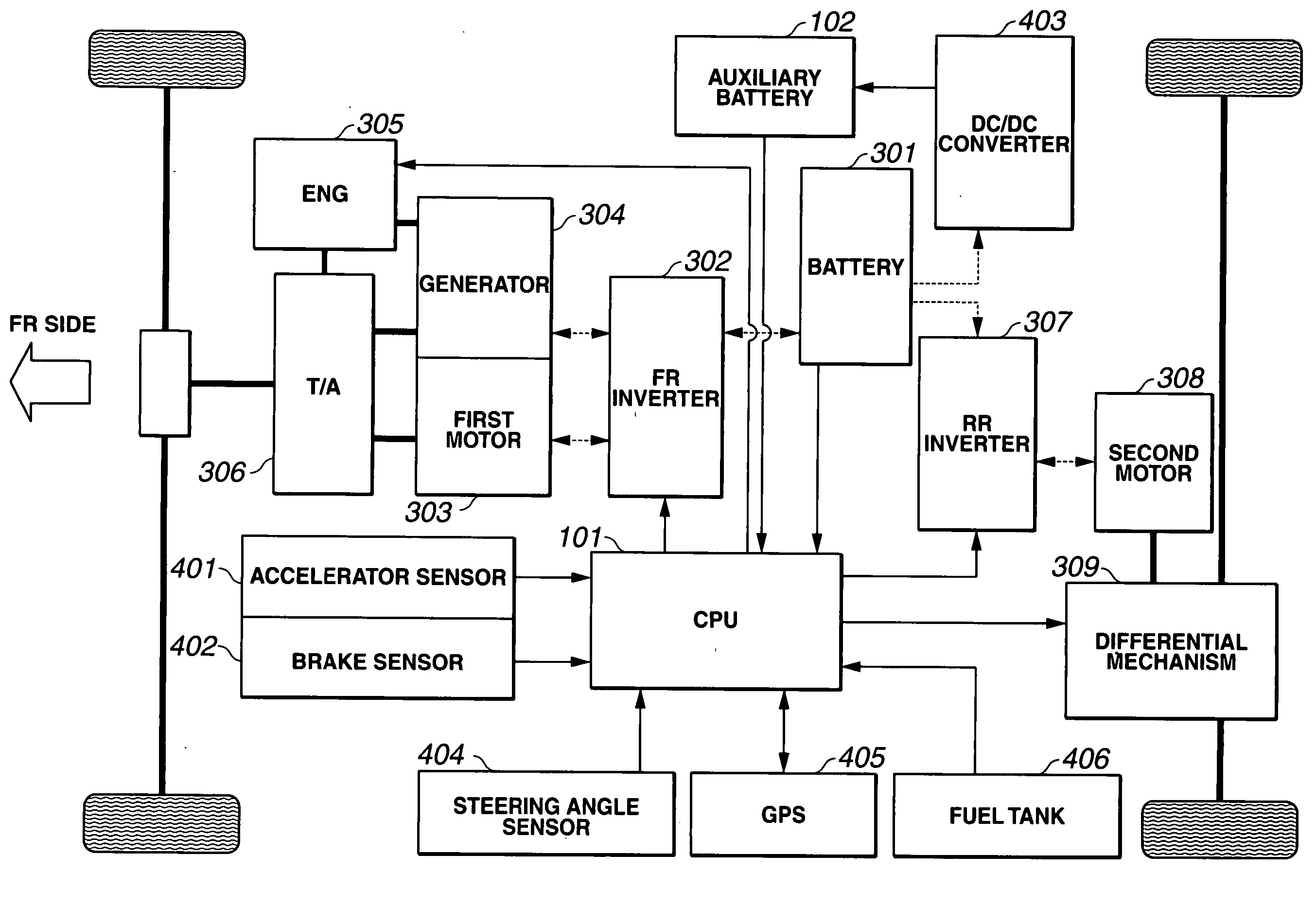
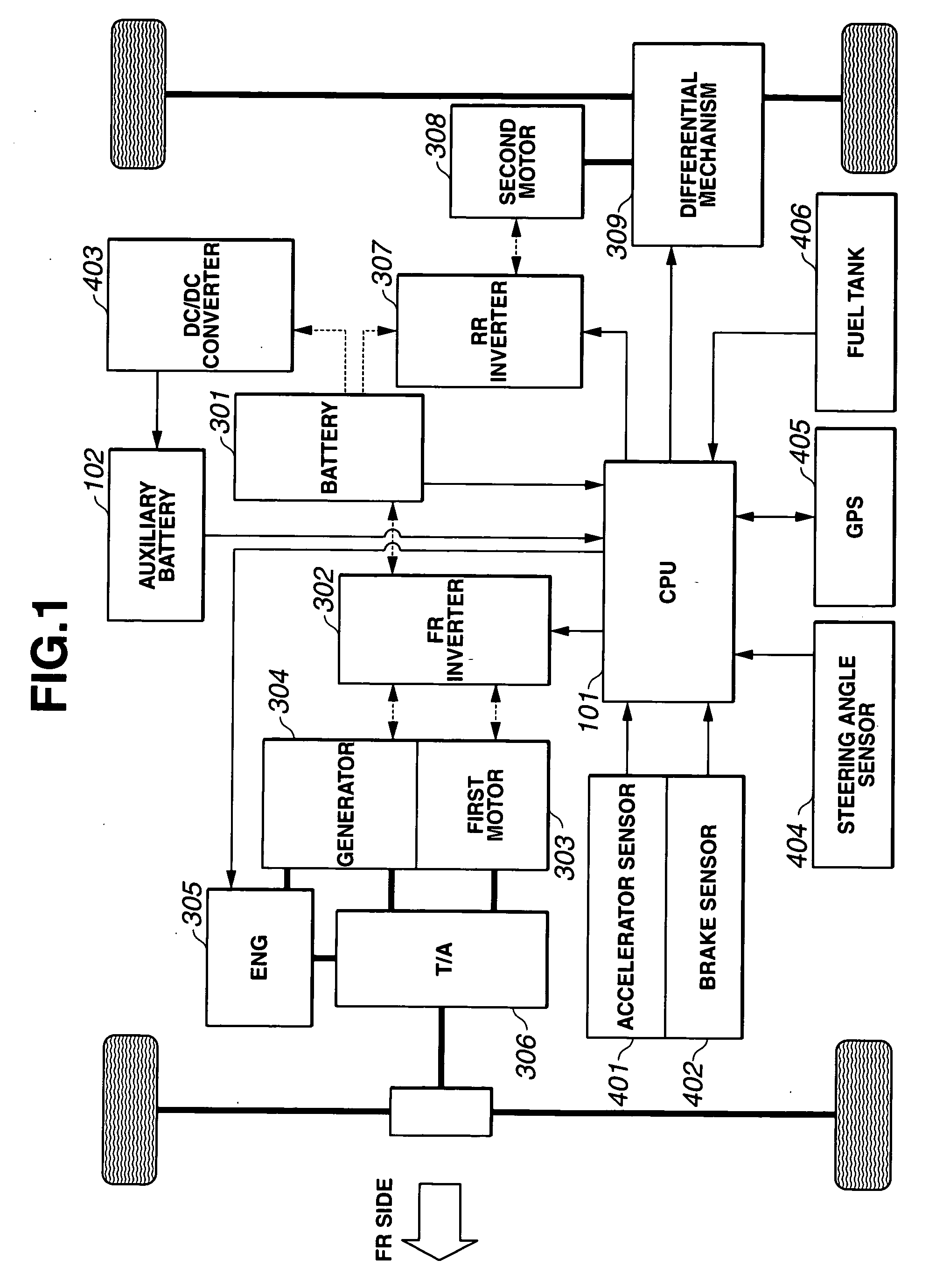
[0026] At first, a configuration of a first embodiment according to the present invention will now be explained. FIG. 1 is a schematic block diagram showing a hybrid four-wheel-drive vehicle employing a driving-force distribution control apparatus of the first embodiment according to the present invention. The hybrid four-wheel-drive vehicle in the first embodiment includes a CPU (central processing unit) 101, an auxiliary battery 102, a battery (strong battery or highly chargeable battery) 301, a FR inverter 302, a first motor( / generator) 303, a generator 304, an engine 305, a power dividing mechanism 306, a RR inverter 307, a second motor( / generator) 308, a differential mechanism (driving-force dividing mechanism for left and right road wheels) 309, an accelerator sensor 401, a brake sensor 402, a DC-DC converter 403, a steering angle sensor 404, a GPS (topography information gathering section) 405, and a fuel tank 406, as shown in FIG. 1.

[0027] CPU 101 i...

second embodiment

[0086] [Second Embodiment]

[0087] A configuration of a second embodiment according to the present invention will now be explained. In the second embodiment; the corners to which the driving-force distribution control will be applied are prioritized after imposing the output limitation on first motor 303, in the case where the remaining amount of liquid fuel is small as the result of checking the remaining amount of liquid fuel.

[0088] S1nce a system configuration in the second embodiment is substantially same as the first embodiment as shown in FIG. 1 except for the following process to be executed in CPU 101, the similar explanations as the first embodiment and a drawing of the configuration of second embodiment will be omitted. Namely in CPU 101, the topography information is gathered by GPS 405; the remaining amount of liquid within fuel tank 406 and a driving route information including the estimated friction coefficient of road surface, the tuning degree (turning radius) and a g...

third embodiment

[0118] [Third Embodiment]

[0119] In a third embodiment according to the present invention; the driving-force distribution control for rear left and right wheels is carried out, by driving each of the rear left and right wheels by means of a corresponding motor.

[0120] At first, a configuration of the third embodiment will now be explained. FIG. 14 is a schematic block diagram showing a hybrid four-wheel-drive vehicle employing a driving-force distribution control apparatus of the third embodiment. The hybrid four-wheel-drive vehicle in the third embodiment includes CPU (central processing unit) 101, auxiliary battery 102, battery (strong battery or highly chargeable battery) 301, FR inverter 302, first motor( / generator) 303, generator 304, engine 305, power dividing mechanism 306, RR inverter 307, second motor( / generator) 308, a third motor( / generator) 310, accelerator sensor 401, brake sensor 402, DC-DC converter 403, steering angle sensor 404, GPS 405, and fuel tank 406, as shown i...


PUM


Abstract

A driving-force distribution control apparatus for a vehicle includes a first motor adapted to drive one of front wheels and rear wheels, as main drive wheels; a second motor adapted to drive another of the front wheels and the rear wheels, as auxiliary drive wheels; an engine adapted to drive the main drive wheels; a battery connected electrically with the first motor and the second motor; an upper-limit output setting section configured to set an upper limit output of the battery in accordance with a charge state of the battery; and a driving-force distribution control section. This driving-force distribution control section is configured to control an output of the first motor and an output of the second motor in accordance with a running condition of the vehicle, to bring a steer characteristic of the vehicle closer to a neutral steer. Moreover, the driving-force distribution control section is configured to impose an output limitation on only the first motor between the first motor and the second motor, when a desired total output of the first motor and the second motor becomes greater than the upper limit output of the battery.

Description

BACKGROUND OF THE INVENTION [0001] The present invention relates to apparatus and / or method for controlling a distribution of driving force of a vehicle having an engine, a first motor, and a second motor. [0002] Japanese Patent Application Publication No. 2004-222413 (patent document D1) discloses a hybrid four-wheel-drive vehicle equipped with an engine, a first motor mechanically coupled with the engine and front wheels and electrically coupled with a battery, and a second motor mechanically coupled with rear wheels and electrically coupled with the battery. [0003] Moreover, Japanese Patent Application Publication No. 2004-189067 (patent document D2) discloses a (non-hybrid) four-wheel-drive vehicle in which front-to-rear distribution ratio and left-to-right distribution ratio of rear wheels are controlled in order to achieve a neutral steer. In this technique, the front-to-rear distribution ratio is continuously varied in the range between 30:70 and 70:30, and the left-to-right ...

Claims


Application Information

Patent Timeline
Patent Type & Authority Applications(United States)
IPC IPC(8): B60K17/356B60K6/44B60K6/52B60K17/348B60L50/16B60W10/04B60W10/06B60W10/08B60W10/10B60W10/119B60W10/12B60W10/20B60W10/26B60W20/00B60W30/00B60W40/10B60W40/109B60W40/114F02D29/02F02D45/00F02M37/00
CPCB60K1/02B60K6/44B60K6/52B60K17/356B60W10/06B60W10/08B60W20/00B60W30/02B60W2510/246B60W2560/02Y02T10/623Y02T10/6265Y02T10/6286B60W2510/244B60W2720/403B60W2720/406B60W2530/209Y02T10/62B60W30/18145B60W20/13
Inventor SUGIMOTO, TOMONAGAMORINAGA, HATSUKI
Owner NISSAN MOTOR CO LTD
Why Eureka
Try Eureka