Position tracking system

a tracking system and position technology, applied in the direction of direction finders, television systems, instruments, etc., can solve the problems of tracking system losing track of objects, inaccuracy of tilt and pan signals generated by processors, and skewing of camera signals, so as to achieve the effect of quick installation

Active Publication Date: 2006-09-07
RGT UNIV OF MICHIGAN
View PDF15 Cites 29 Cited by
  • Summary
  • Abstract
  • Description
  • Claims
  • Application Information

AI Technical Summary

Benefits of technology

[0015] When the loop is disposed around an object that rotates relative to the infrared-sensitive device, such as a person, a constantly unimpeded viewing channel is provided between the infrared-sensitive device and at least one of the elements due to the positioning of the elements on opposite sides of the loop, which therefore positions the elements on opposite sides of the person's body. As a result, the infrared-sensitive device can constantly track the elements such that tracking with the infrared-sensitive device is unimpeded. Further, in order to use the position tracking system, the loop may be installed quickly by only placing the loop around a person's neck, waist, or other appendage and turned on. The infrared light-emitting elements are also capable of passing light through clothing, hair, paper, etc. so that the loop may be hidden beneath clothing, if desired. Further, the loop appears as an indiscrete accessory and is not distracting to observers of the person being tracked.

Problems solved by technology

With the tracking system of the '291 publication, other moving objects may be in the field of view of the cameras, thereby skewing the signals generated by the cameras and causing inaccuracies in the tilt and pan signals generated by the processor.
Further, if the moving object were to enter an area of direct sunlight or other bright light, the visible light camera may detect a washed image in the area of the direct light, thus causing the tracking system to lose track of the object.
The object may move behind other objects within a field of view of the camera, which may obscure the object from view and cause the tracking system to lose track of the object.
With the tracking system of the '709 patent, the object having the mark affixed thereto may move behind other objects within a field of view of the camera, thus obscuring the mark from view and causing the tracking system to lose track of the mark.
Further, the mark may be obscured beneath clothing, thereby causing the tracking system to lose track of the mark.
Further obstruction may occur simply by the object rotating relative to the infrared camera, thereby obscuring the mark from view behind the rotating object.
The infrared light may also reflect off of shiny surfaces, thereby skewing the signals generated by the infrared camera and causing the tracking system to lose track of the object.
However, the cameras have a fixed field of view and cannot follow the sensors if the sensors move from the fixed field of view of the cameras.
With the sensors being positioned at different points on the body, installation of the sensors is cumbersome and time consuming.
As such, the tracking system of the '637 patent is not suitable for all manner of position tracking applications.
Further, no hair or clothing can cover the sensors.
Such features make the tracking system of the '421 patent cumbersome and may distract a person wearing the infrared transmitter.
By scanning for a peak signal strength, the sensor of the '421 patent is susceptible to ambient infrared light reflecting off of shiny objects, as well as other sources of infrared light.
Finally, as shown in the Installation and Operations Manuals, although the infrared transmitter may include infrared light-emitting elements disposed along a loop, a control box is not part of the loop and must be separately connected to the loop through a cable, thus making the infrared transmitter bulky and distracting.

Method used


Image

  • Position tracking system
  • Position tracking system
  • Position tracking system

Examples


Embodiment Construction

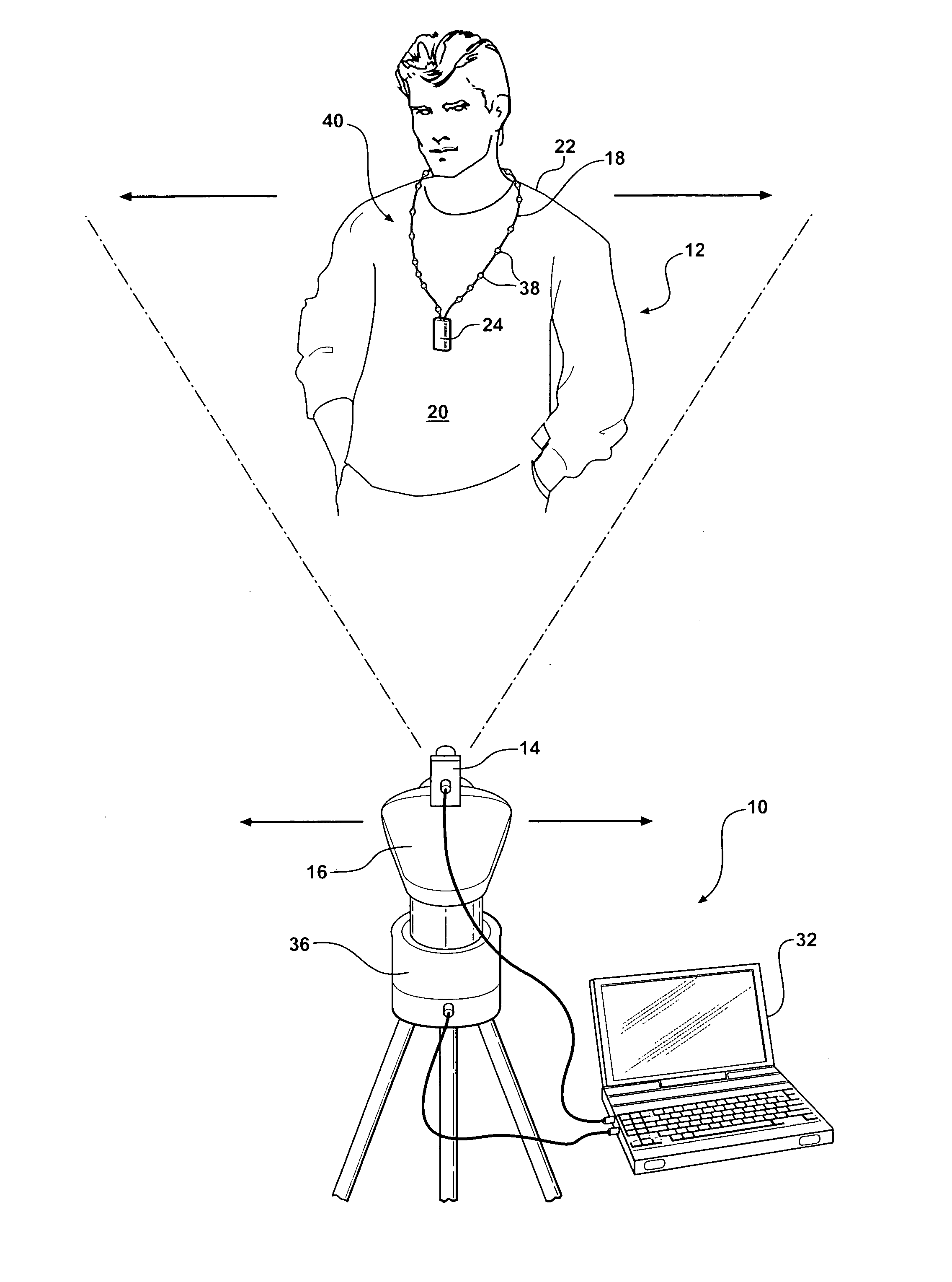
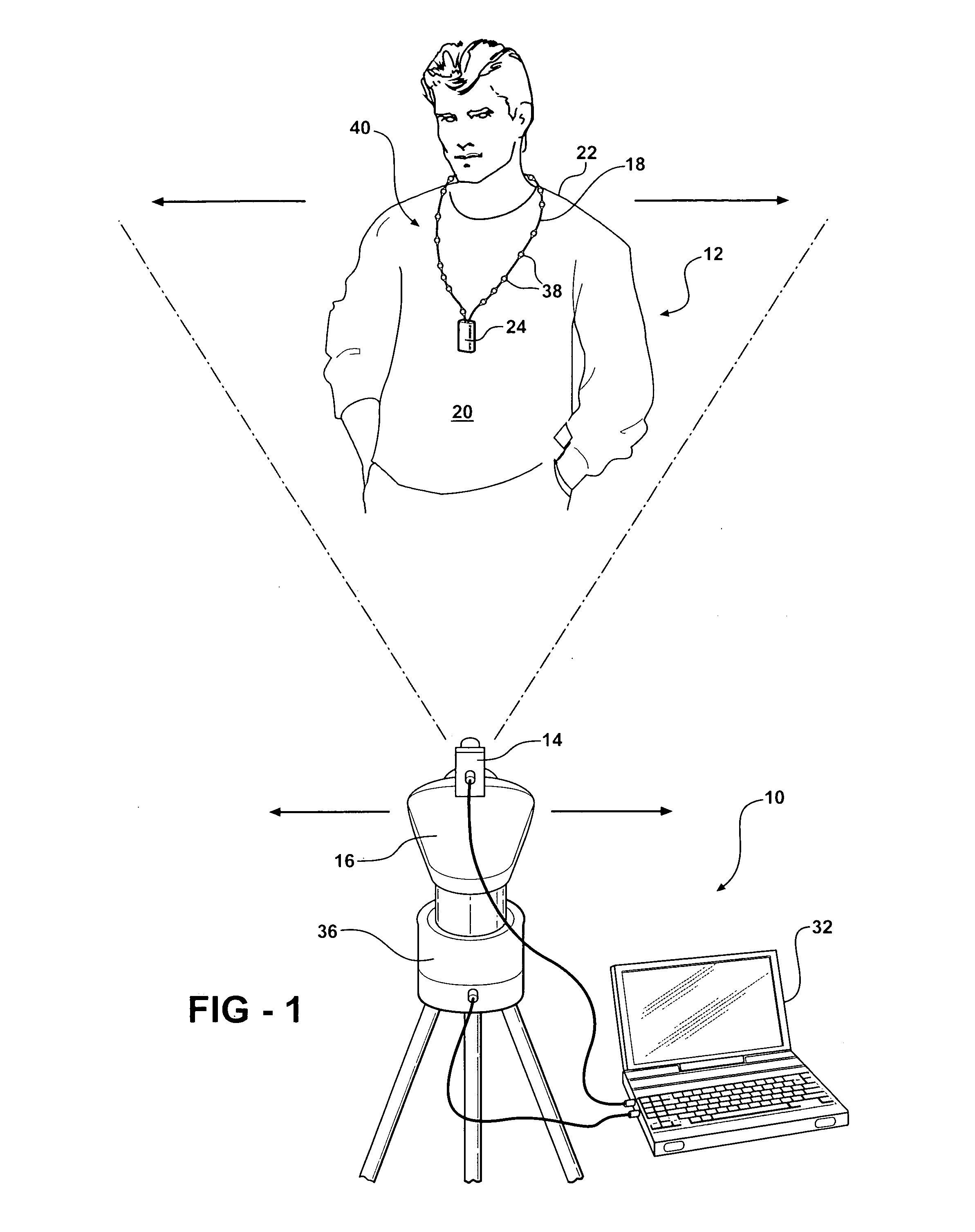
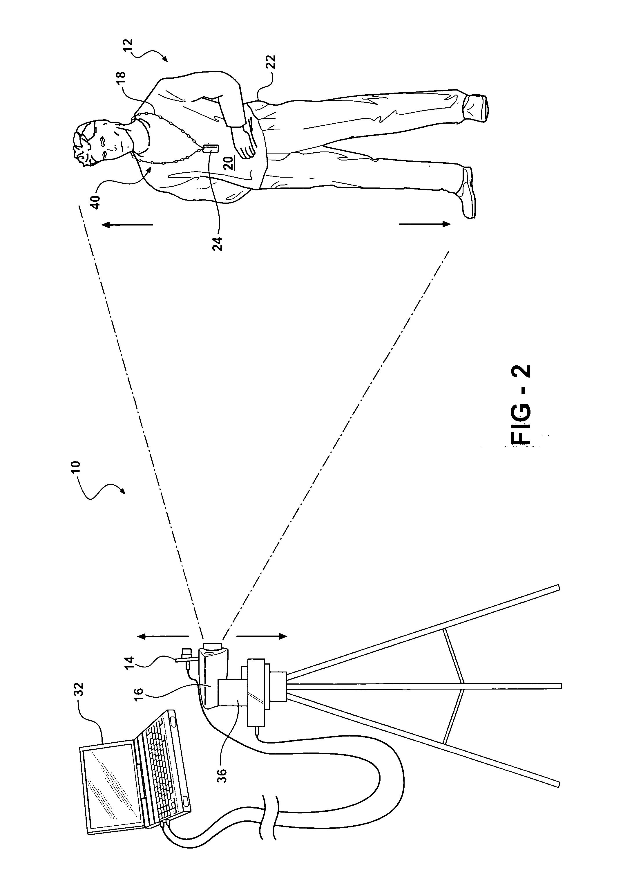
[0024] Referring to the Figures, wherein like numerals indicate corresponding parts throughout the several views, a position tracking system is shown generally at 10 in FIGS. 1 and 2. One of the contemplated uses for the position tracking system 10 is for tracking the movement of a lecturer 12 during a lecture or a seminar to enable a visible-light video camera 14 to track and record the lecturer 12 as the lecturer 12 moves around. The lecture or seminar may be recorded and stored for future use, used to network in remote attendees, and / or disseminated over the internet. The position tracking system 10 eliminates a need for a human camera operator, which adds expense to recording the lectures or seminars on video. It is contemplated that by using the position tracking system 10 of the present invention, a large volume of lectures may be recorded and archived without the expenses that typically accompany recording lectures. Although the position tracking system 10 of the present inve...


PUM


Abstract

A position tracking system includes an infrared-sensitive device, such as an infrared camera that generates signals in response to detected infrared light in a field of view of the infrared-sensitive device. A processor is responsive to the signals generated by the infrared-sensitive device for determining a position of the detected infrared light. The processor also generates tilt and pan signals based on the position of the detected infrared light. A tilt and pan mechanism moves a visible-light video camera in response to the tilt and pan signals from the processor. The active infrared light-emitting device includes a loop having at least two infrared light-emitting elements disposed along the loop, on opposite sides of the loop. A control box is disposed in the loop and is in electrical communication with the infrared light-emitting elements. When the loop is disposed around an object that rotates relative to the infrared-sensitive device, a constantly unimpeded viewing channel is provided between the infrared-sensitive device and at least one of the elements due to the positioning of the elements. The position information obtained from the infrared-sensitive device is used to direct a visible-light camera to track the active infrared light-emitting device in a manner similar to that performed by a human camera operator.

Description

CROSS REFERENCE TO RELATED APPLICATION [0001] This application claims the benefit of U.S. Provisional Application Ser. No. 60 / 659,139 filed Mar. 7, 2005.GOVERNMENT LICENSE RIGHTS [0002] The U.S. Government has a paid-up license in this invention and the right in limited circumstances to require the patent owner to license others on reasonable terms as provided for by the terms of grant number 0333580 awarded by the National Science Digital Library division of the National Science Foundation.BACKGROUND OF THE INVENTION [0003] 1. Field of the Invention [0004] The subject invention generally relates to a position tracking system. More specifically, the subject invention relates to a position tracking system that includes an infrared-sensitive device for detecting infrared light, a processor for determining a position of the detected infrared light and for generating tilt and pan signals based on the position, and a tilt and pan mechanism for moving a visible-light video camera in respo...

Claims


Application Information

Patent Timeline
Patent Type & Authority Applications(United States)
IPC IPC(8): H04N5/225
CPCG01S3/7864G01S5/16
Inventor NEAL, HOMER A.YE, CANGHERR, JEREMYIRRER, JAMES C.
Owner RGT UNIV OF MICHIGAN
Why Eureka
Try Eureka