Transflective display device

a display device and display technology, applied in non-linear optics, instruments, optics, etc., can solve the problems of low power consumption of reflective fpd devices, large power consumption of devices, and poor visibility of transmissive fpd devices in very bright environments, so as to achieve less reflection area, better and more efficient reflection, and more transmission area

Inactive Publication Date: 2006-09-07
HON HAI PRECISION IND CO LTD
View PDF22 Cites 4 Cited by
  • Summary
  • Abstract
  • Description
  • Claims
  • Application Information

AI Technical Summary

Benefits of technology

[0012] An advantage of the FPD device is that the reflective nano-particles provide better and more efficient reflection, and thus less reflection area is needed and more transmission area can be used for transmitting the backlight.
[0013] Another advantage of the FPD device is that the transmission / reflection ratio of the transflective layer can be determined by controlling the quantity, size distribution, and reflectivity of the reflective nano-particles.
[0014] A further advantage of the FPD device is that better color saturation can be obtained by appropriately designing the reflective nano-particle size distribution.
[0015] A still further advantage of the FPD device is that the transflective layer can be integrated as a whole into a thinner substrate, thus saving production cost.

Problems solved by technology

A transmissive FPD device is capable of producing a bright image with a high contrast ratio without being substantially influenced by the brightness of the environment, but such a device consumes a lot of power due to the backlight.
Moreover, a transmissive FPD device has a poor visibility under very bright environments (e.g., when used outdoor under a clear sky).
On the other hand, a reflective FPD device consumes little power, but the brightness and the contrast ratio thereof are liable to be influenced by the conditions, under which it is used, e.g., the brightness of the environment.
However, since parts of the transflective layer are transmissive and the others are not, a conventional transflective FPD usually has no way to give better attention to its transmission ability and its reflection ability.
As a result, an FPD device having such a configuration typically cannot provide a satisfactory color saturation.

Method used


Image

  • Transflective display device
  • Transflective display device
  • Transflective display device

Examples


Embodiment Construction

[0021] Reference will now be made to the drawings to describe the preferred embodiments of the present FPD device, in detail.

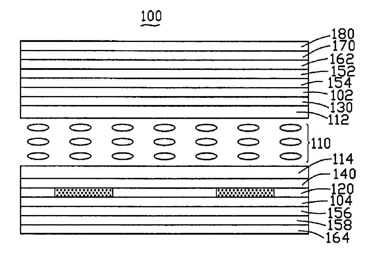
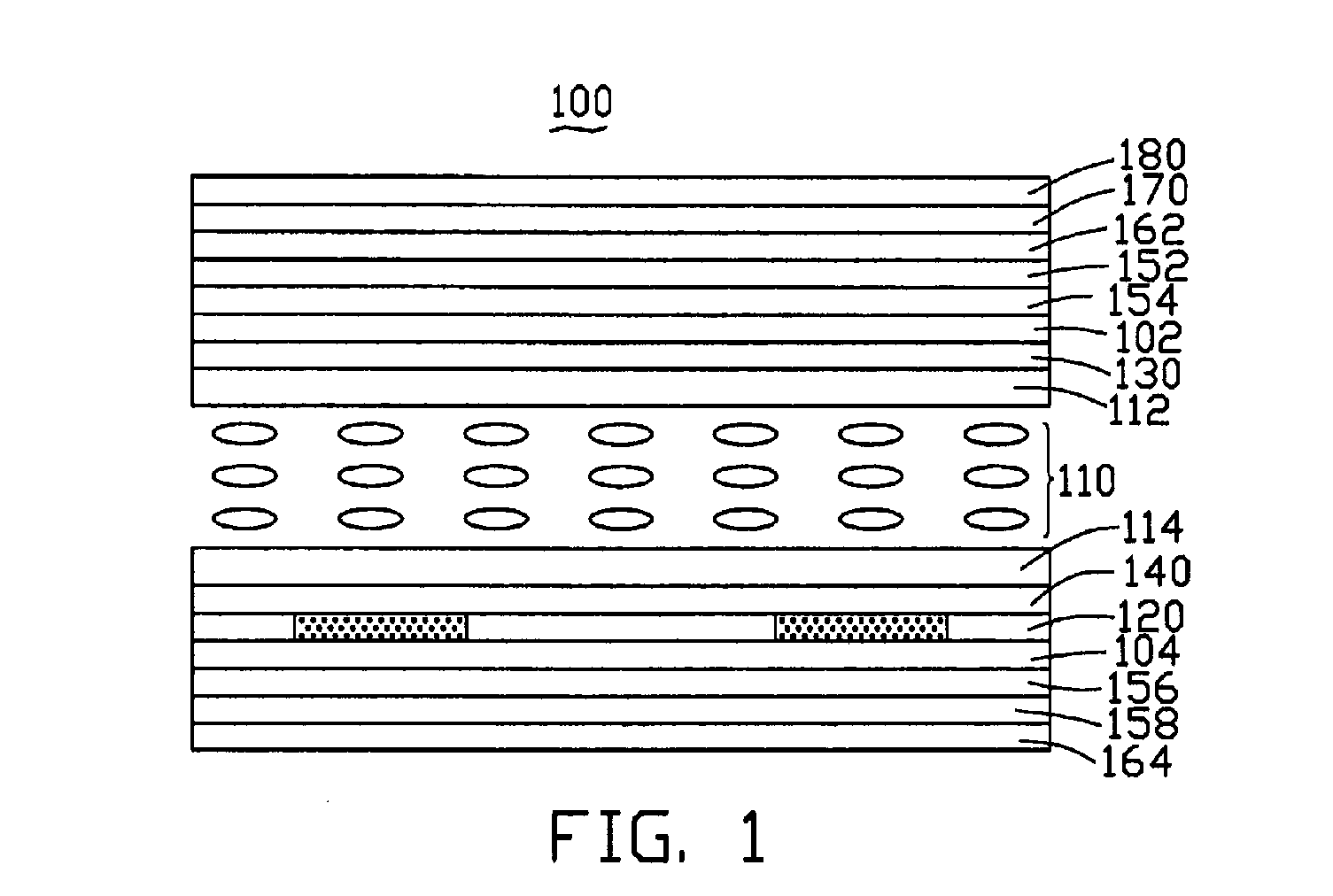
[0022] Referring now to the drawings, and more particularly to FIG. 1, there is shown a transflective FPD device 100. The transflective FPD device 100 mainly includes an upper substrate 102, a lower substrate 104, a liquid crystal layer 110, a transflective layer 120, a thin film transistor (TFT) layer 130, a color filter layer 140, an upper polarizer 162, and a lower polarizer 164.

[0023] The liquid crystal layer 110 is interposed between the upper substrate 102 and the lower substrate 104 and includes a plurality of liquid crystal molecules. The liquid crystal layer 110 further includes an upper alignment film 112, and a lower alignment film 114. The liquid crystal molecules are received between the upper alignment film 112 and the lower alignment film 114. The upper alignment film 112 and the lower alignment film 114 are adapted for aligning the liquid cry...


PUM

PropertyMeasurementUnit
grain sizesaaaaaaaaaa
sizesaaaaaaaaaa
brightnessaaaaaaaaaa

Abstract

A transflective FPD device is provided. The transflective FPD device includes a liquid crystal layer and a transflective layer. The tansflective layer includes a matrix made of a transparent material and a plurality of reflective nano-particles. The reflective nano-particles are configured for reflecting ambient light and are dispersed uniformly and randomly in the entire matrix. The transflective layer is adapted for reflecting ambient lights, and as well as for allowing backlight to pass therethrough.

Description

CROSS-REFERENCES TO RELATED APPLICATION [0001] This application is related to a copending U.S. patent application entitled “A TRANSFLECTIVE DISPLAY DEVICE” with the same assignee. The disclosure of the above-identified application is incorporated herein by reference. [0002] 1. Field of the Invention [0003] The present invention relates to a transflective display device and, particularly, to a transflective flat panel display (FPD) device. [0004] 2. Description of Related Art [0005] Conventional FPD devices are generally classified into reflective devices and transmissive devices. A transmissive FPD device displays an image by using light emitted from a backlight source, and a reflective FPD displays an image by using ambient light. [0006] A transmissive FPD device is capable of producing a bright image with a high contrast ratio without being substantially influenced by the brightness of the environment, but such a device consumes a lot of power due to the backlight. Moreover, a tra...

Claims


Application Information

Patent Timeline
Patent Type & Authority Applications(United States)
IPC IPC(8): G02F1/1335
CPCG02F1/133555
Inventor CHEN, GA-LANE
Owner HON HAI PRECISION IND CO LTD
Why Eureka
Try Eureka