Radio communication device and radio communication method

a radio communication and radio communication technology, applied in multiplex communication, orthogonal multiplex, high-level techniques, etc., can solve the problems of reducing the amount of control signal transmitted, increasing the power consumption of the mobile station, and reducing the data capacity of the transmission. , the effect of reducing power consumption

Active Publication Date: 2006-09-07
OPTIS WIRELESS TECH LLC
View PDF20 Cites 42 Cited by
  • Summary
  • Abstract
  • Description
  • Claims
  • Application Information

AI Technical Summary

Benefits of technology

[0014] It is an object of the present invention to provide a wireless communication apparatus and reception quality reporting method capable of increasing the data capacity that can be transmitted

Problems solved by technology

However, with wireless communication apparatus of the conventional art, the quantity of signal required for CQI reporting is enormous.
Further, as

Method used


Image

  • Radio communication device and radio communication method
  • Radio communication device and radio communication method
  • Radio communication device and radio communication method

Examples


embodiment 1

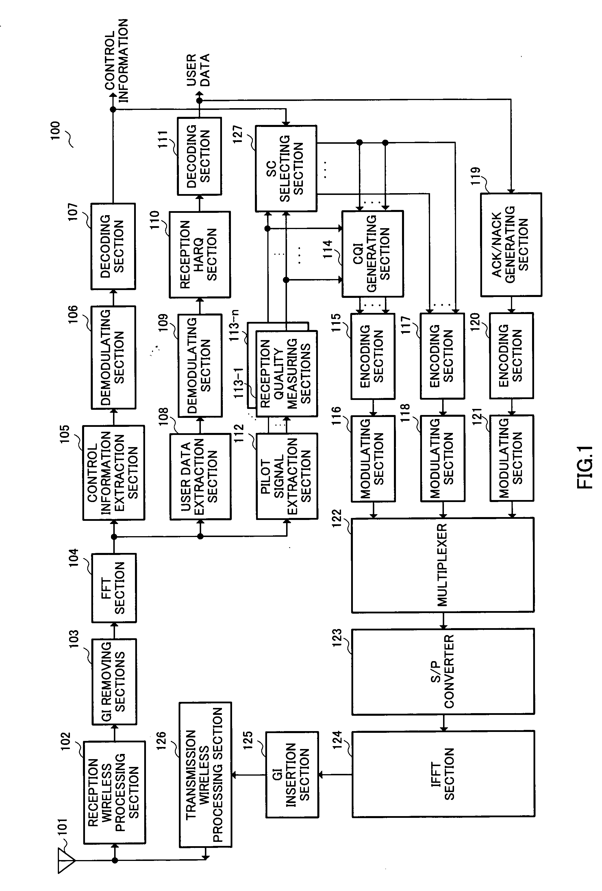
[0034]FIG. 1 is a block diagram showing a configuration of wireless communication apparatus 100 of Embodiment 1 of the present invention.

[0035] Reception wireless processing section 102 down converts and suchlike a received signal received at antenna 101 from a radio frequency to a baseband frequency and outputs to guard interval (hereinafter referred to as “GI”) removing section 103.

[0036] GI removing section 103 removes GI's from a received signal inputted from reception wireless processing section 102 and then outputs to fast Fourier transform (hereinafter referred to as “FFT; Fast Fourier Transform”) section 104.

[0037] After converting the received signal inputted from GI removing section 103 from a serial data format to a parallel data format, FFT section 104 subjects the received signal to FFT and outputs to control information extraction section 105, user data extraction section 108 and pilot signal extraction section 112.

[0038] Control information extraction section 105 ...

embodiment 2

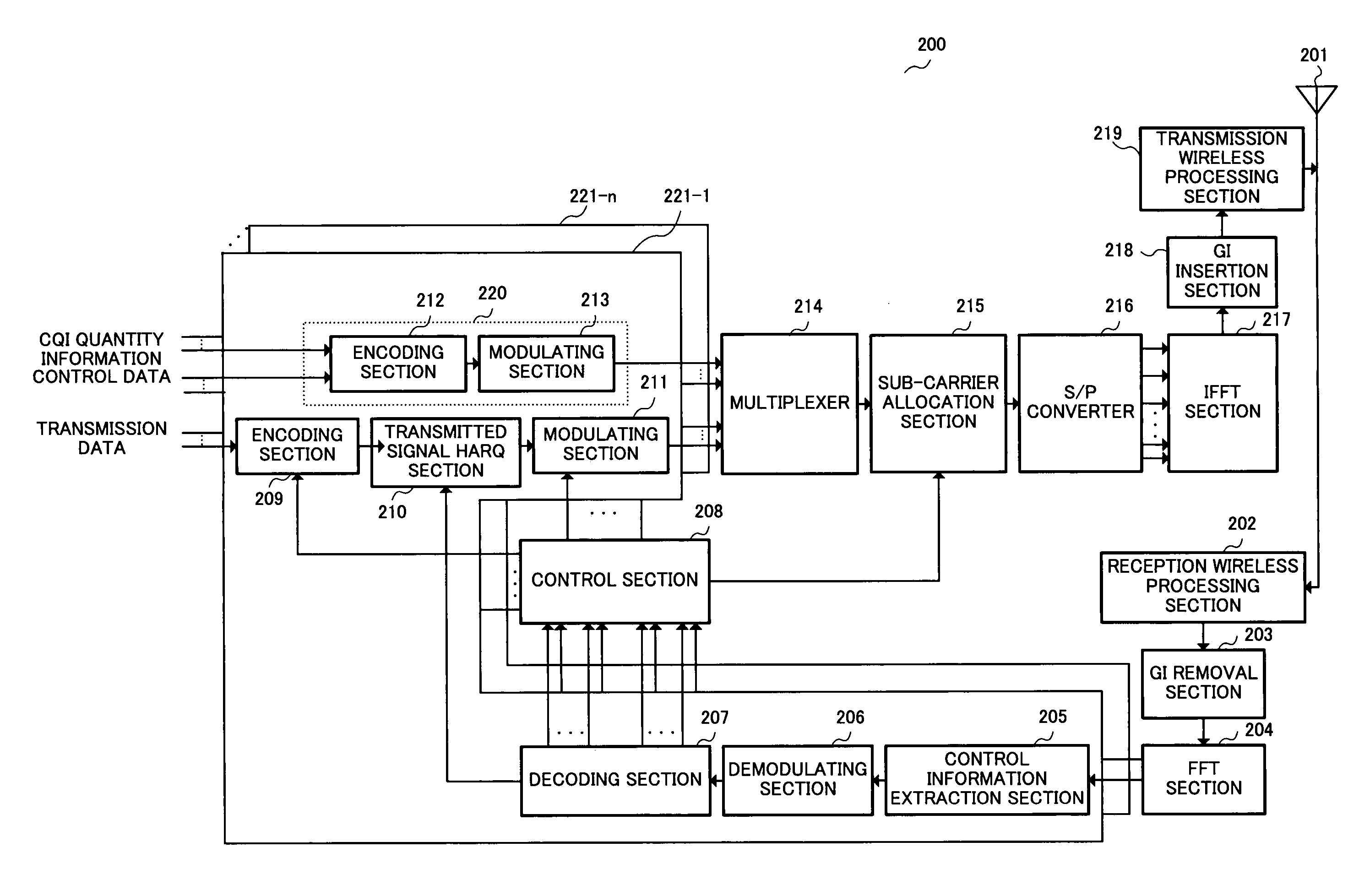
[0127]FIG. 6 is a block diagram showing a configuration for a wireless communication apparatus 600 according to Embodiment 2 of the present invention.

[0128] As shown in FIG. 6, wireless communication apparatus 600 according to Embodiment 2 is of a configuration where SC selecting section 127 is omitted and a threshold value determining section 601 is added in wireless communication apparatus 100 of Embodiment 1 shown in FIG. 1.

[0129] In FIG. 6, portions with the same configuration as for FIG. 1 are given the same numerals and are not described.

[0130] Further, the configuration of the base station apparatus with the exception of sending CQI threshold value information instead of CQI quantity information is the same as the configuration of FIG. 2 and is therefore not described.

[0131] Decoding section 107 decodes demodulated control information inputted by demodulating section 106 and outputs control information, and outputs CQI threshold value information contained in the control ...

embodiment 3

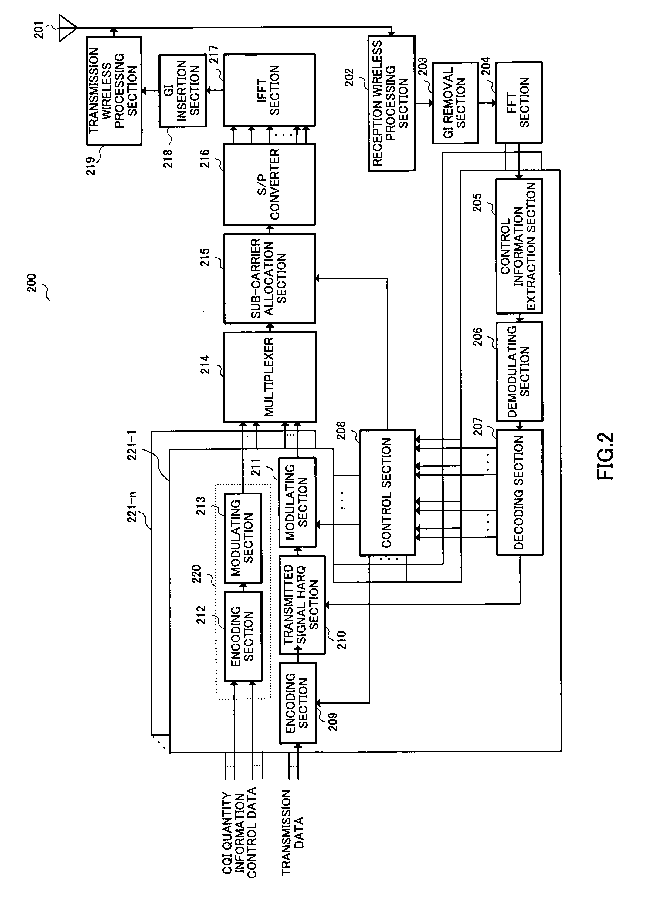
[0144]FIG. 7 is a block diagram showing a configuration of a wireless communication apparatus 700 according to Embodiment 3 of the present invention.

[0145] As shown in FIG. 7, wireless communication apparatus 700 of Embodiment 3 is of a configuration where encoding section 117, demodulating section 118, and SC selecting section 127 are removed, and threshold value determining section 701, used sub-carrier selecting section 702 and spreading section 703 are added in wireless communication apparatus 100 of Embodiment 1 shown in FIG. 1.

[0146] In FIG. 7, portions with the same configuration as for FIG. 1 are given the same numerals and are not described.

[0147] CQI generating section 114 generates CQI's for each sub-carrier for all of the sub-carriers using measurement value information inputted by reception quality measuring section 113.

[0148] In other words, CQI generating section 114 has a reference table that stores information for CQI selection use to which different CQI's are a...


PUM


Abstract

A wireless communication apparatus is capable of increasing data capacity that can be transmitted and reducing power consumption by reducing the amount of control signal to be transmitted, and capable of increasing system capacity by reducing interference with respect to other wireless communication apparatuses.
In this apparatus, control information extraction section (105) extracts information indicating the number of CQI's contained in control information.
Reception quality measuring sections (113-1 to 113-n) measure reception quality of each sub-carrier within a communication band.
CQI generating section (114) generates CQI's for some of the sub-carriers of superior reception quality within the communication band.
Multiplexer (122) multiplexes CQI's, sub-carrier number information generating the CQI's, and ACK signals or NACK signals.
The SC selecting section (127) then selects the number of sub-carriers from a base station apparatus of superior reception quality allocated using the CQI quantity designation information.

Description

TECHNICAL FIELD [0001] The present invention relates to a wireless communication and reception quality reporting method, and particularly relates to a wireless communication apparatus and reception quality reporting method for performing high-speed packet communication using adaptive modulation and scheduling. BACKGROUND ART [0002] In a conventional art, in HSDPA (High-SpeedDownlink Packet Access) of 3GPP, adaptive modulation where the modulation scheme is adaptively controlled according to propagation path conditions and scheduling for transmitting a user signal for which propagation path conditions are comparatively superior have been employed in downlink high-speed packet transmission. [0003] In multi-carrier transmission such as OFDM and MC-CDMA (for example, Hara, Kawabata, Duan and Sekiguchi, “MC-CDM System for Packet Communications Using Frequency Scheduling”, TECHNICAL REPORT OF IEICE, RCS2002-129, July 2002, refer to pp. 61-66) being examined as transmission schemes for bey...

Claims


Application Information

Patent Timeline
IPC IPC(8): H04B7/00H04J11/00H04B7/216H04B1/00H04B1/707H04B7/26H04LH04W28/22H04W72/04H04W72/08H04W72/12H04W76/02
CPCH04L1/0026H04L1/1671H04L5/003H04L5/0044H04L5/0046Y02B60/50H04L5/006H04W28/06H04W72/1231H04W72/1284H04W24/10H04L5/0053Y02D30/70H04W72/542H04W72/21H04W72/23H04W72/0453H04B7/26H04W8/02H04W72/54H05K999/99
Inventor NISHIO, AKIHIKOCHENG, JUN
Owner OPTIS WIRELESS TECH LLC
Why Eureka
Try Eureka