Wireless communication apparatus and wireless communication method
a wireless communication and wireless communication technology, applied in the field of wireless communication and reception quality reporting methods, can solve the problems of shortened battery life, increased power consumption of mobile stations, and enormous signal quantity for cqi reporting, so as to reduce power consumption, reduce the amount of control signal transmitted, and increase the data capacity. the effect of transmission
- Summary
- Abstract
- Description
- Claims
- Application Information
AI Technical Summary
Benefits of technology
Problems solved by technology
Method used
Image
Examples
embodiment 1
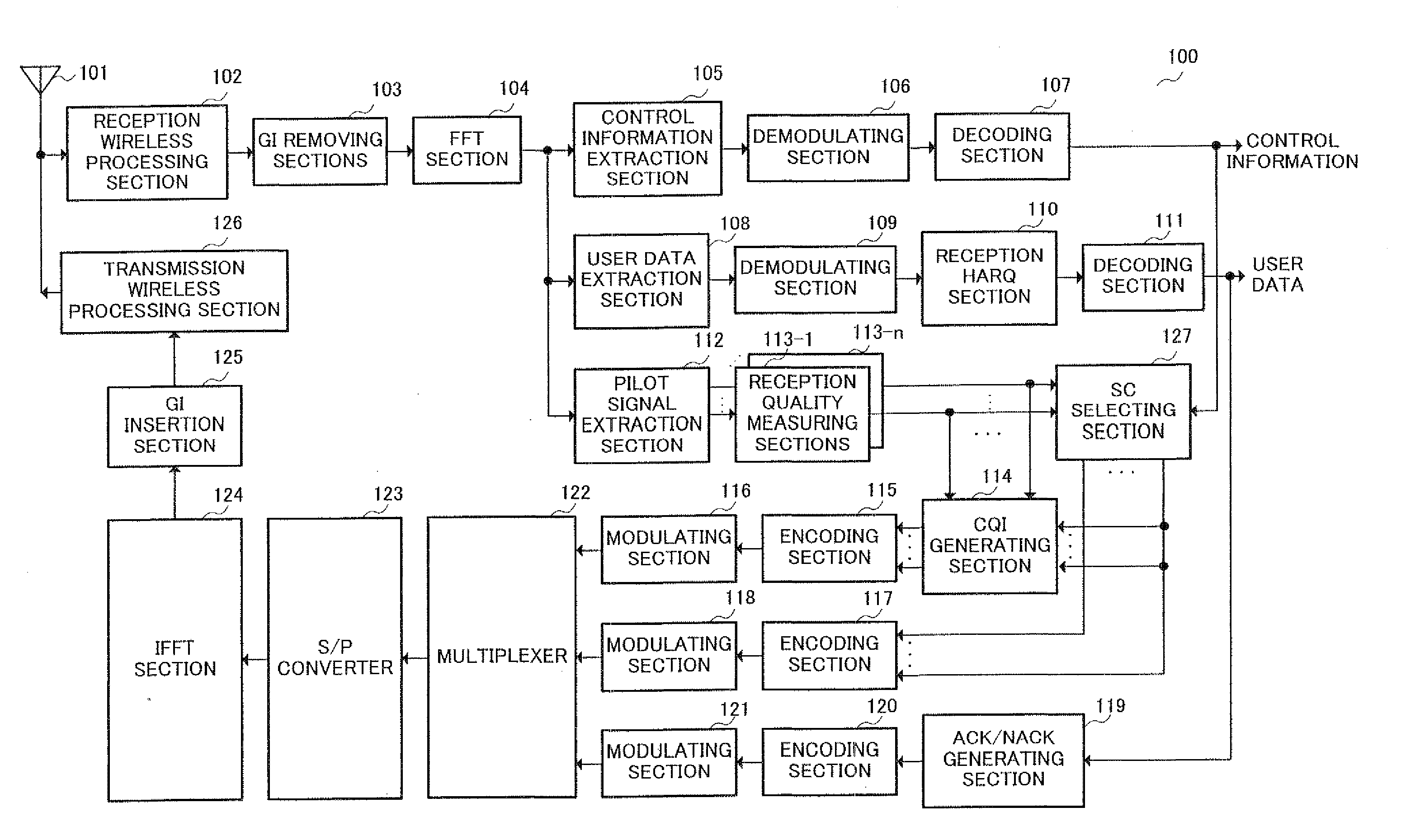
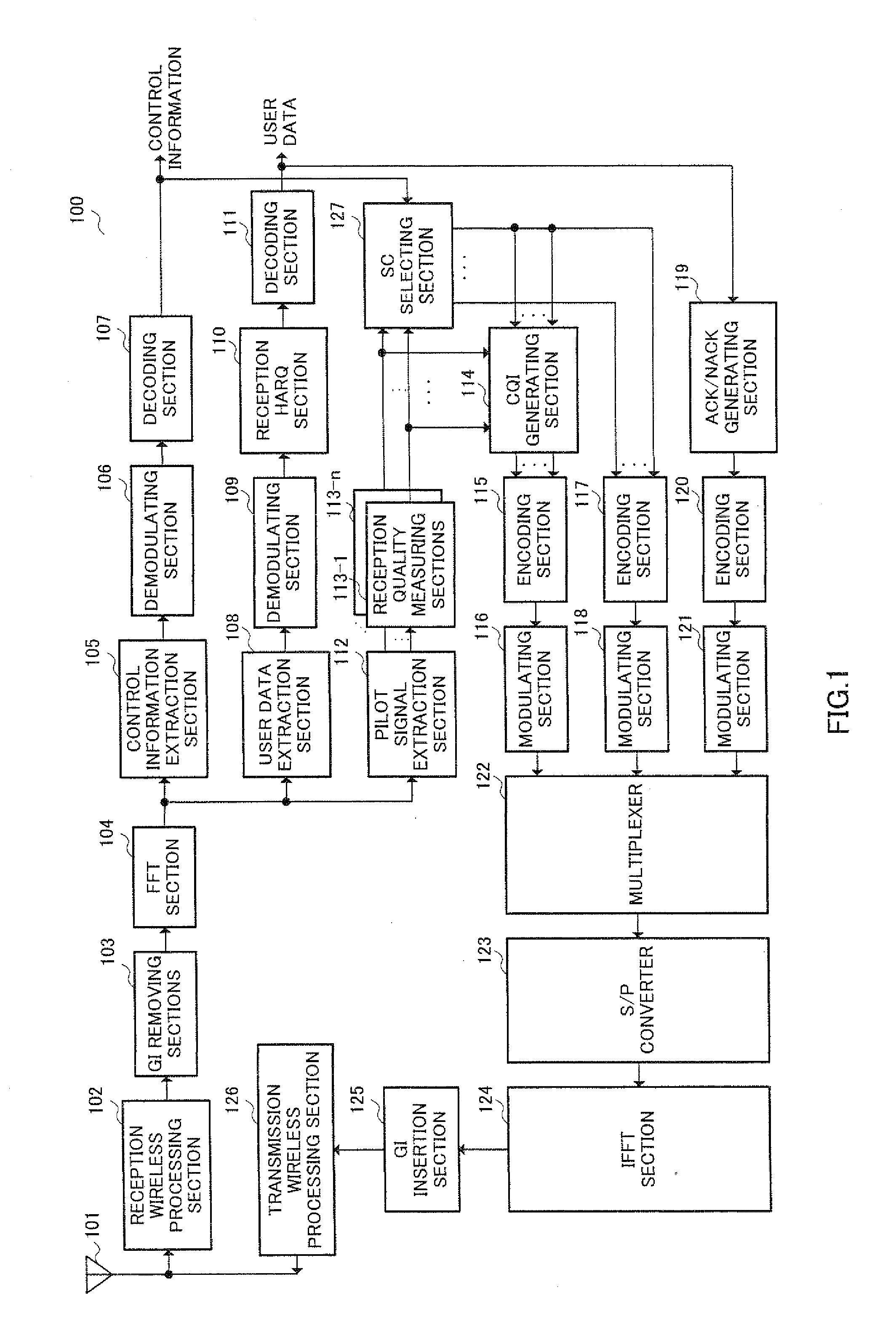
[0035]FIG. 1 is a block diagram showing a configuration of wireless communication apparatus 100 of Embodiment 1 of the present invention.
[0036]Reception wireless processing section 102 down converts and suchlike a received signal received at antenna 101 from a radio frequency to a baseband frequency. and outputs to guard interval (hereinafter referred to as “GI”) removing section 103.
[0037]GI removing section 103 removes GI's from a received signal inputted from reception wireless processing section 102 and then outputs to fast Fourier transform (hereinafter referred to as “FFT; Fast Fourier Transform”) section 104.
[0038]After converting the received signal inputted from GI removing section 103 from a serial data format to a parallel data format, FFT section 104 subjects the received signal to FFT and outputs to control information extraction section 105, user data extraction section 108 and pilot signal extraction section 112.
[0039]Control information extraction section 105 extract...
embodiment 2
[0129]FIG. 6 is a block diagram showing a configuration for a wireless communication apparatus 600 according to Embodiment 2 of the present invention.
[0130]As shown in FIG. 6, wireless communication apparatus 600 according to Embodiment 2 is of a configuration where selecting section 127 is omitted and a threshold value determining section 601 is added in wireless communication apparatus 100 of Embodiment 1 shown in FIG. 1.
[0131]In FIG. 6, portions with the same configuration as for FIG. 1 are given the same numerals and are not described.
[0132]Further, the configuration of the base station apparatus with the exception of sending CQI threshold value information instead of CQI quantity information is the same as the configuration of FIG. 2 and is therefore not described.
[0133]Decoding section 107 decodes demodulated control information inputted by demodulating section 106 and outputs control information, and outputs CQI threshold value information contained in the control information...
embodiment 3
[0146]FIG. 7 is a block diagram showing a configuration of a wireless communication apparatus 700 according to Embodiment 3 of the present invention.
[0147]As shown in FIG. 7, wireless communication apparatus 700 of Embodiment 3 is of a configuration where encoding section 117, demodulating section 118, and SC selecting section 127 are removed, and threshold value determining section 701, used sub-carrier selecting section 702 and spreading section 703 are added in wireless communication apparatus 100 of Embodiment 1 shown in FIG. 1.
[0148]In FIG. 7, portions with the same configuration as for FIG. 1 are given the same numerals and are not described.
[0149]CQI generating section 114 generates CQI's for each sub-carrier for all of the sub-carriers using measurement value information inputted by reception quality measuring section 113.
[0150]In other words, CQI generating section 114 has a reference table that stores information for CQI selection use to which different CQI's are allocated...
PUM
 Abstract
Description
Claims
Application Information
 - R&D
- Intellectual Property
- Life Sciences
- Materials
- Tech Scout
- Unparalleled Data Quality
- Higher Quality Content
- 60% Fewer Hallucinations
Browse by: Latest US Patents, China's latest patents, Technical Efficacy Thesaurus, Application Domain, Technology Topic, Popular Technical Reports.
© 2025 PatSnap. All rights reserved.Legal|Privacy policy|Modern Slavery Act Transparency Statement|Sitemap|About US| Contact US: help@patsnap.com


