Laser scanning unit including a shield

a laser scanning and shield technology, applied in the direction of laser details, optical resonator shape and construction, instruments, etc., can solve problems such as printing defects, and achieve the effect of reducing or blocking ghosting ligh

Active Publication Date: 2006-09-07
LEXMARK INT INC
View PDF10 Cites 15 Cited by
  • Summary
  • Abstract
  • Description
  • Claims
  • Application Information

AI Technical Summary

Benefits of technology

[0005] This need is met by the present invention, wherein a shield is provided for reducing or blocking ghosting light generated in a laser scanner unit having a single polygonal mirror reflecting a plurality of laser beams impinging upon the mirror and further including opp

Problems solved by technology

The ghosting light may be re-reflected off the polygonal

Method used


Image

  • Laser scanning unit including a shield
  • Laser scanning unit including a shield
  • Laser scanning unit including a shield

Examples


Embodiment Construction

[0034] In the following detailed description of the preferred embodiment, reference is made to the accompanying drawings that form a part hereof, and in which is shown by way of illustration, and not by way of limitation, specific preferred embodiments in which the invention may be practiced. It is to be understood that other embodiments may be utilized and that changes may be made without departing from the spirit and scope of the present invention.

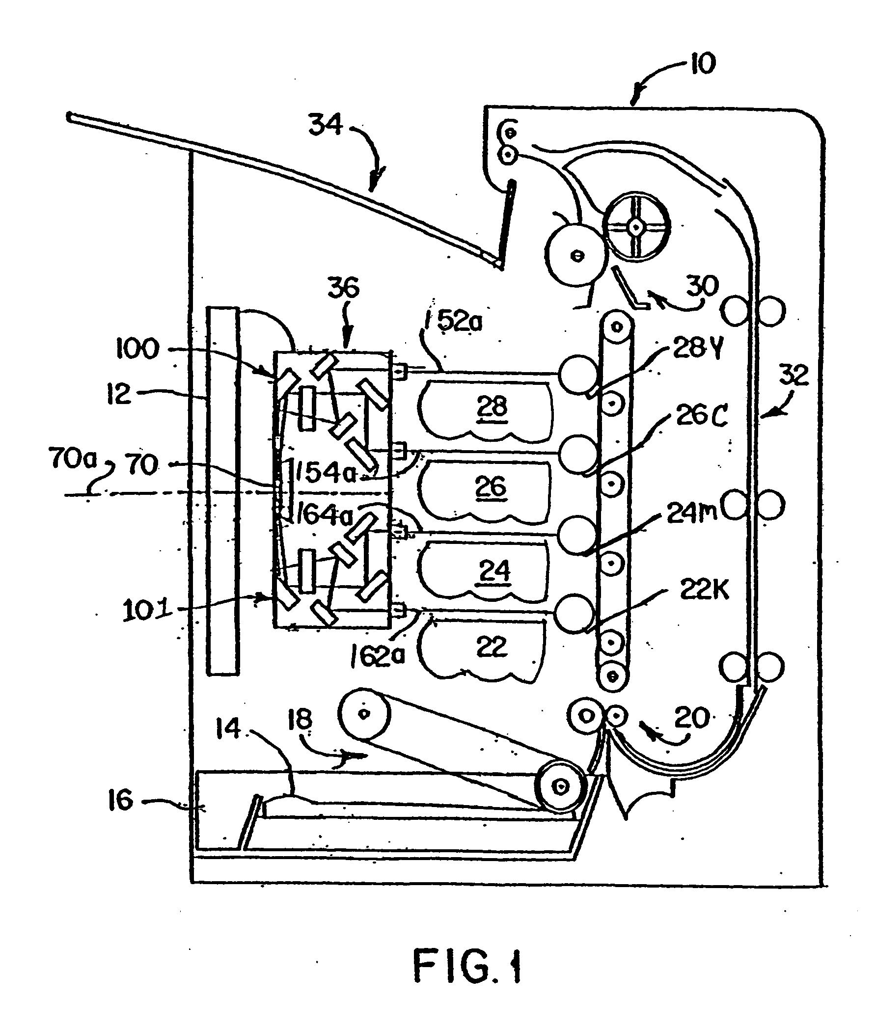
[0035]FIG. 1 depicts a representative electrophotographic image forming apparatus, such as a color laser printer, which is indicated generally by the numeral 10. An image to be printed is electronically transmitted to a controller 12 by an external device (not shown). The controller 12 includes system memory, one or more processors, and other logic necessary to control the functions of electrophotographic imaging.

[0036] In performing a printing operation, the controller 12 initiates an imaging operation where a top sheet 14 of a stack ...


PUM


Abstract

A laser scanning unit is provided comprising: a housing; a scanning device; a first pre-scan assembly generating a first light beam and directing the first light beam toward the scanning device; a second pre-scan assembly generating a second light beam and directing the second light beam toward the scanning device; a first post-scan assembly receiving the first light beam reflected from the scanning device and causing a first portion of the first light beam to scan along a first scan path; and a second post-scan assembly receiving the second light beam reflected from the scanning device and causing a first portion of the second light beam to scan along a second scan path. The first post-scan assembly further reflects a second portion of the first light beam in a direction away from the first scan path. A shield is associated with the housing for blocking the second portion of the first light beam reflected by the first post-scan assembly during at least a portion of the scan of the first portion of the first light beam along the first scan path so as to prevent the second portion of the first light beam from entering the second post-scan assembly.

Description

TECHNICAL FIELD AND INDUSTRIAL APPLICABILITY OF THE INVENTION [0001] The present invention relates generally to a laser scanning unit, and more particularly, to such a unit having a shield for blocking at least a portion of laser light energy reflected by a post-scan assembly. BACKGROUND OF THE INVENTION [0002] Laser scanning units are known comprising a laser diode for generating a laser beam, a rotating polygonal mirror for reflecting the laser beam along a scan line on a photoconductive (PC) drum, and post scan optics comprising at least one fΘ lens positioned between the rotating mirror and the PC drum. Ghosting light may be generated by reflection of the laser beam at a surface of a lens forming part of the post-scan optics. The ghosting light may be re-reflected off the polygonal mirror toward the PC drum, thereby causing print defects. A shield covering at least a portion of the polygonal mirror is provided so as to block the ghosting light. [0003] U.S. Pat. No. 5,901,000 dis...

Claims


Application Information

Patent Timeline
IPC IPC(8): H01S3/10H01S3/08
CPCB41J2/473G02B26/121G02B26/123G02B26/125
Inventor HUDSON, RANDALL L.PETERS, DANNY W.
Owner LEXMARK INT INC
Why Eureka
Try Eureka