Light-guide plate

a technology of light-guide plate and light-guide plate, which is applied in the direction of lighting and heating apparatus, instruments, mechanical equipment, etc., can solve the problems of reducing the uniformity of light-guide plate emission, affecting the light-guide plate uniformity, and affecting the light-guide plate light-guide angle, etc., to achieve the effect of reducing the haz

Inactive Publication Date: 2006-09-07
WINTEK CORP
View PDF3 Cites 22 Cited by
  • Summary
  • Abstract
  • Description
  • Claims
  • Application Information

AI Technical Summary

Benefits of technology

[0007] Consequently, for solving the abovementioned problems, the present invention proposes the light-guide facet of the light-guide structure presenting an arc-surface configuration which lets the deflected light keep the directional characteristic and have the effect of light-diffusion for a certain extent at the same time. By way of this, the drawback of narrow emitting angle due to the too high directional characteristic for the well-known light-guide structures can be mended. Hence, the light guide plate does not need to use a diffuser or only needs to use a diffuser with lower haze. The brightness of the backlight module is further upgraded at the same time.

Problems solved by technology

However, the light-guide structure of this design method will make the deflected light from the light-guide plate to be concentrated in a narrow area, and the deflected light beam is concentrated (as shown in FIG. 2) such that a drawback of smaller view angle is resulted.
Moreover, adjusting the uniformity of emitting light for the light-guide plate 1 becomes difficult.
Although using a diffuser can solve the problem mentioned above, the light-diffusion capability of the diffuser is still difficult to control.
Controlling the light diffused by a diffuser in a certain range of angle is very hard.
As a result, the cost of the manufacturing process rises substantially.
Besides, during the injection-molding process for the light-guide plate 1, the too small and too dense light-guide structure 2 results in ill forming such that the qualities of produced light-guide plates 1 are unstable.

Method used


Image

  • Light-guide plate
  • Light-guide plate
  • Light-guide plate

Examples


Embodiment Construction

[0032] The detailed descriptions for content and technology of this invention associate with figures are as followings.

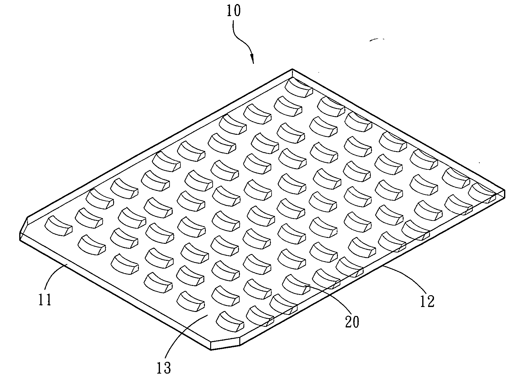
[0033] Please refer to FIGS. 4 and FIGS. 5. FIGS. 4 is an embodiment of a schematic diagram showing a light-guide plate having randomly arranged light-guide structures of the present invention. FIG. 5 is an enlarged schematic diagram showing a first preferred light-guide structure of the present invention. The present invention is related to a transparent light-guide plate 10 and arc shaped light-guide structures 20 thereon. The light-guide plate 10 is used in a backlight module that uses at least one light-emitting element as the light source. The light-guide plate 10 includes one light-incident facet 11, one bottom facet 12 extended from one side of the light-incident facet 11, one light-output facet 13 opposite to the bottom facet 12, and a plurality of light-guide structures 20 (the configuration shown in the FIG. 5 is only one single light-guide structure 20) ...


PUM


Abstract

A light-guide plate and its light-guide structures that are formed at the plate body of the light-guide plate in a concave configuration, a bottom side of the light-guide facet of the light-guide structures that face to the light source approximately presents an arc-like shape. The arc-like shape makes the light after deflecting have the effect of diffusion for a certain extent. These light-guide structures present a sparse-to-dense distribution along the direction that is away from the light source. The arc angles of the bottom side of the light-guide structures present a large-to-small configuration along the direction that is away from the light source such that the whole brightness of the light-guide plate is uniform.

Description

FIELD OF THE INVENTION [0001] The present invention relates to a light-guide plate and aims to make a change of the light-guide structure inside the light-guide plate such that the deflected light has the effect of diffusion for a certain extent and the directional characteristic so as to let the light-guide plate emit light uniformly. BACKGROUND OF THE INVENTION [0002] Please refer to FIG. 1. The light from the light source 3 is reflected or refracted by the light-guide structure 2 and emitted outward from the light guide for conventional light-guide plate. The merit of this light-guiding mechanism is that the light deflected by the light-guide structure 2 has a strong directionality. Because the angle between the deflected light and the normal direction of the emitting facet of the light-guide plate become lower via reflection or refraction, the limitation of the total reflection is broken and the light can be deflected out of the light-guide plate 1. Moreover, the light can be gu...

Claims


Application Information

Patent Timeline
Patent Type & Authority Applications(United States)
IPC IPC(8): G02B6/10F21V8/00
CPCG02B6/0036
Inventor FANG, CHONG-YANGCHEN, PING-YENGHUANG, KUO-JUI
Owner WINTEK CORP
Why Eureka
Try Eureka