

Noninvasive targeting system method and apparatus
a targeting system and non-invasive technology, applied in the field of non-invasive sampling, can solve the problems of inability to efficiently collect diffusely reflected light, inaccurate and inability to generate accurate and precise non-invasive analyte property determination in reproducible fashion, so as to increase the accuracy and sampling precision. , the effect of increasing the accuracy
- Summary
- Abstract
- Description
- Claims
- Application Information
AI Technical Summary
Benefits of technology
Problems solved by technology
Method used
Image

Examples
example i
[0094] In one example, the distance or relative distance between the sample probe tip and the sample site is determined using a single capacitor. The sample probe is brought into close proximity with the sample site using the time constant / distance measurement as a metric. In this manner, the sample probe is brought into close proximity to the sample site without displacing the sample site. Due to the inverse relationship between capacitance and distance, the sensitivity to distance between the sample site and the sample probe increases as the distance between the sample probe and the sample site decreases. Using capacitance sensors, the distance between the sample site and the tip of the sample probe is readily directed to a distance of less than about one millimeter. Capacitance sensors as used herein are also readily used to place the sample probe tip with a distance of less than about 0.1 millimeter to the sample site. In this example, multiple capacitors are optionally used to ...
example ii
[0095] In a second example, two or more capacitance sensors are optionally used for leveling the tip of the sample probe relative to the morphology of the sample site. The distance between the sample site and the probe tip is measured using two or more capacitor pairs. For example, if one capacitor reads a larger distance to the sample site than the second capacitor, then the probe tip is moved to level the probe by moving the larger distance side toward the sample, the smaller distance side away from the sample, or both. The sample probe tip tilt or angle is either moved manually or by mechanical means.
Controller
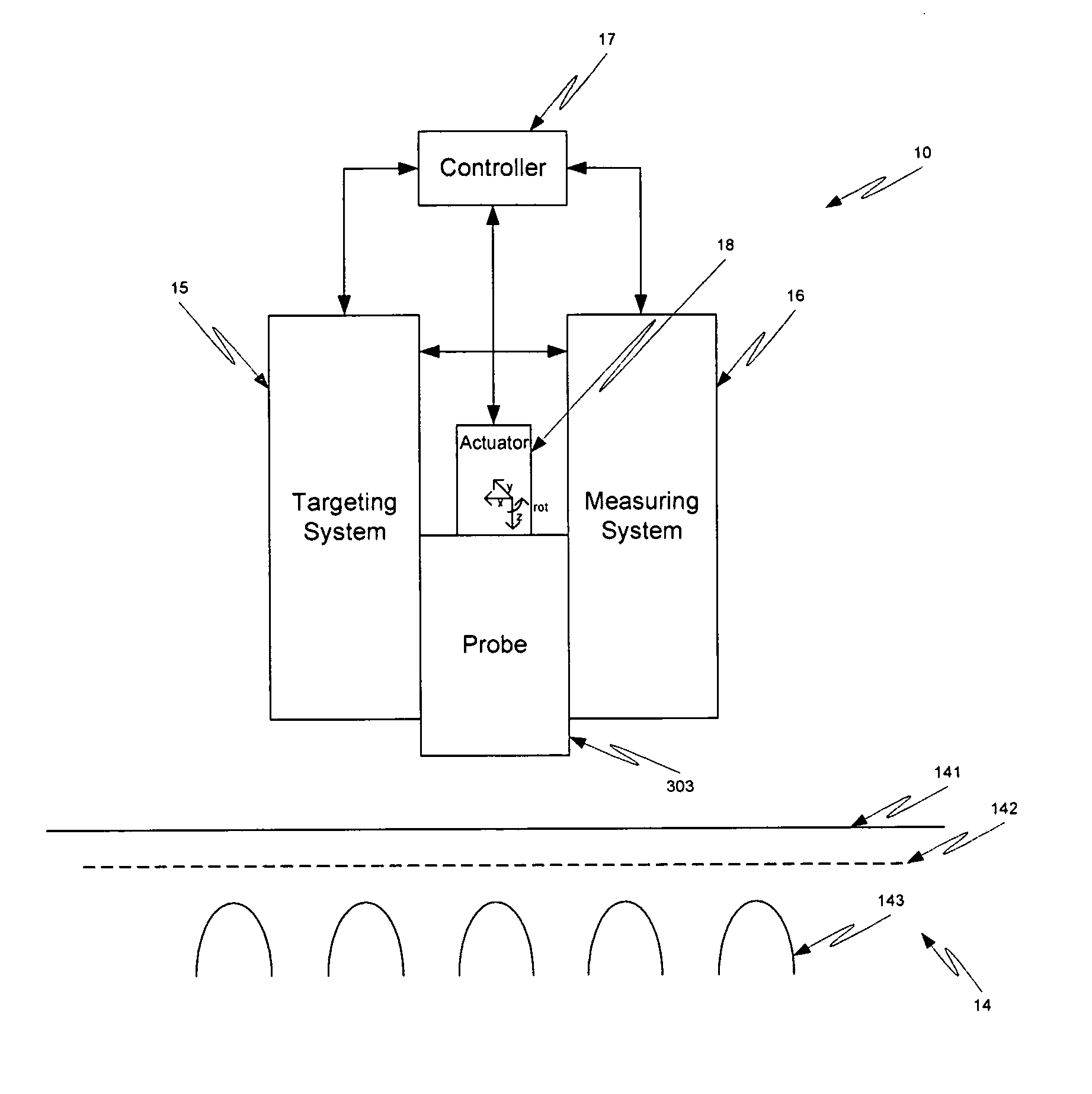
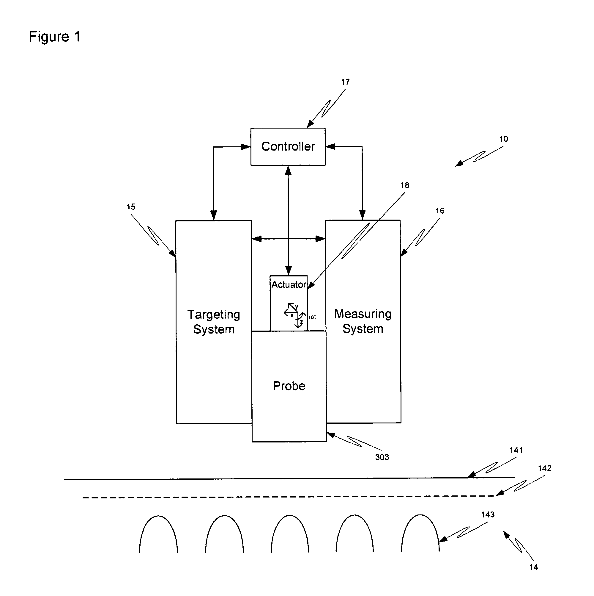
[0096] A controller controls the movement of one or more sample probes via one or more actuators. The controller optionally uses an intelligent system for locating the sample site and / or for determining surface morphology. For example, the controller hunts in the x- and y-axes for a spectral signature. In a second example, the controller moves a sample probe via the actu...
example iii
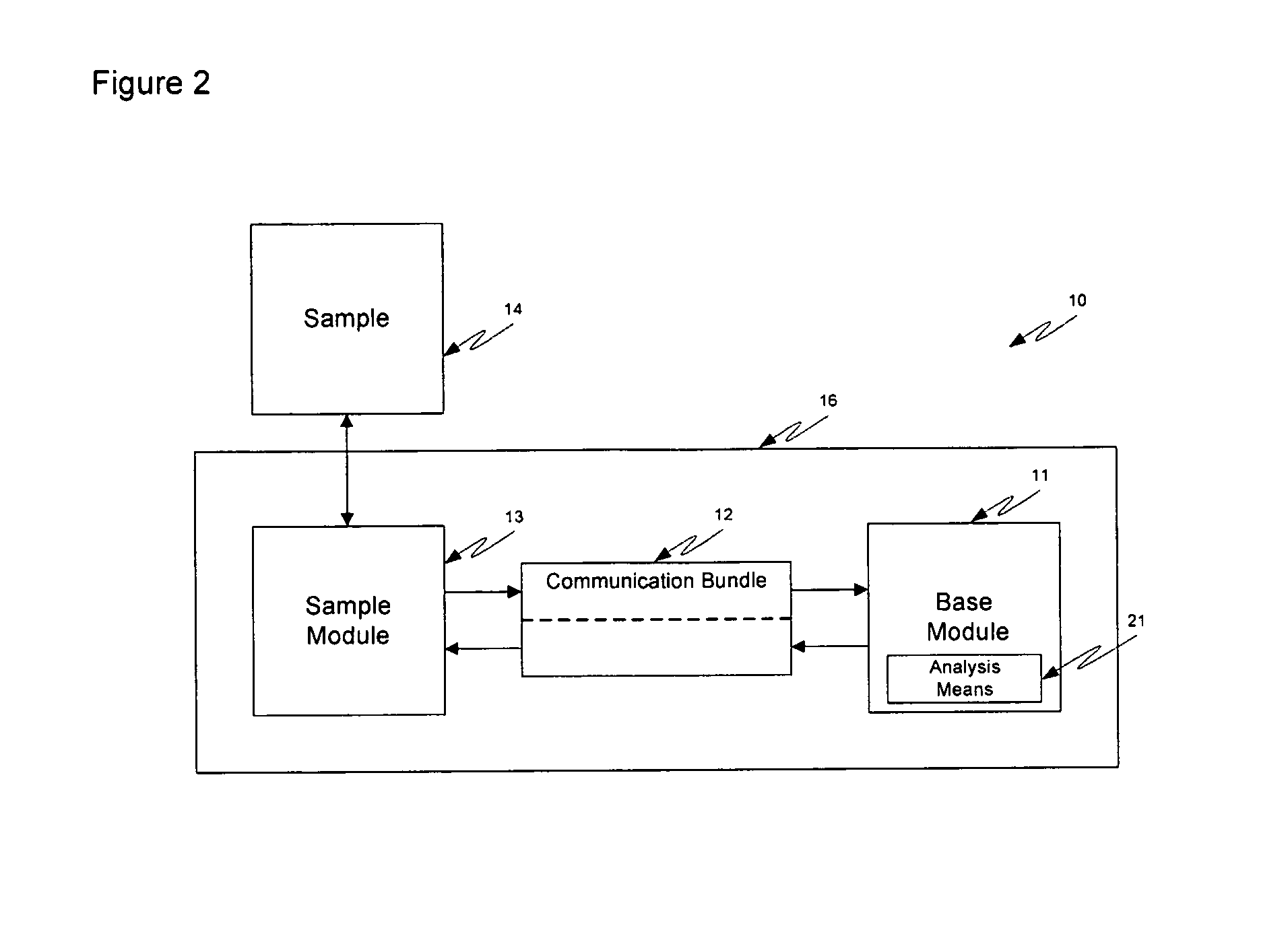
[0111] In one example of the invention, a single source is used for the targeting system and the measuring system. Referring now to FIG. 3, a sample module 13 portion of an analyzer 10 is presented. Within the sample module, photons from source 31 are directed to a sample 14 either directly or via one or more optics, such as a backreflector 32 or a lens. In one case, the incident photons pass through a dichroic filter 33. A portion of the incident photons either reflect off of the surface or are diffusely reflected from a volume of the tissue sample 14. A portion of the specular and / or diffusely reflected photons are directed to a targeting system 15. In this example, the collection optics uses a dichroic filter 33 that reflects a portion of the specular or diffusely reflected to the targeting or imaging system 15. In this example, a collection optic 34, such as a fiber optic, is used to collect diffusely reflected photons. The end of the fiber optic is preferably in close proximity...
PUM
 Abstract
Description
Claims
Application Information