
Polyaxial bone screw assembly

Active Publication Date: 2006-09-07
JACKSON
View PDF13 Cites 125 Cited by
  • Summary
  • Abstract
  • Description
  • Claims
  • Application Information

AI Technical Summary

Benefits of technology

[0015] Therefore, objects of the present invention include: providing an improved spinal implant assembly for implantation into vertebrae of a patient; providing such an assembly that includes a receiver with an open channel, a shank pivotally connected to the receiver, a rod or other structural element, and a compression structure disposed between the shank and the rod for holding the shank at a desired angle of inclination or articulation with respect to the receiver; providing such an assembly that has a low profile after final installation; providing such an assembly in which the compression structure may be inserted into a bone screw receiver prior to installing the bone screw into bone; providing such an assembly in which an upper shank portion of the bone screw includes a non-slip feature for driving the shank into bone; providing such an assembly in which an upper portion

Problems solved by technology

This is sometimes very difficult or impossible to do.
Certain prior art plug type closures have been threadably received between the opposed arms of the bone screw receiver using conventional V-shaped thread forms which has resulted in a significant amount of radially outward pressure or force being applied to the arms of the bone screw receiver.
Such outward force may result in splaying of the arms, after which the closure becomes loose which may either result in a failure of the implant by allowing the rod to slip relative to the bone screw or the closure may even come completely out of the receiver of the bone screw for total failure of the implant.
Bone screw compression inserts may desirably reduce relative motion between the rod and the bone screw, but may be undesirable in practice as they may also require separate insertion during surgery, after implantation of the bone screw shank, and may be small and thus difficult to handle.
Alternatively, compression inserts loaded in a bone screw prior to implantation may obstruct bone screw features utilized for driving the threaded bone screw shank into bone, or require less than desirable modifications in the bone screw, decreasing strength and / or requiring specialized driving tools.

Method used


Image

  • Polyaxial bone screw assembly
  • Polyaxial bone screw assembly
  • Polyaxial bone screw assembly

Examples


Embodiment Construction

[0032] As required, detailed embodiments of the present invention are disclosed herein; however, it is to be understood that the disclosed embodiments are merely exemplary of the invention, which may be embodied in various forms. Therefore, specific structural and functional details disclosed herein are not to be interpreted as limiting, but merely as a basis for the claims and as a representative basis for teaching one skilled in the art to variously employ the present invention in virtually any appropriately detailed structure.

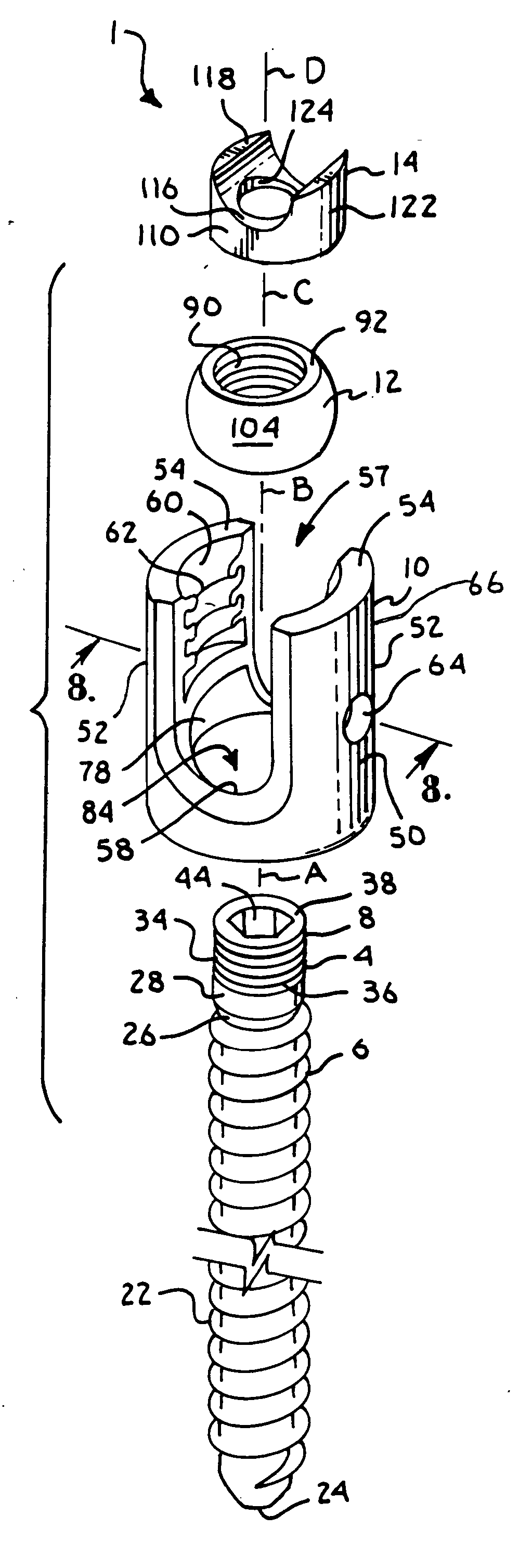
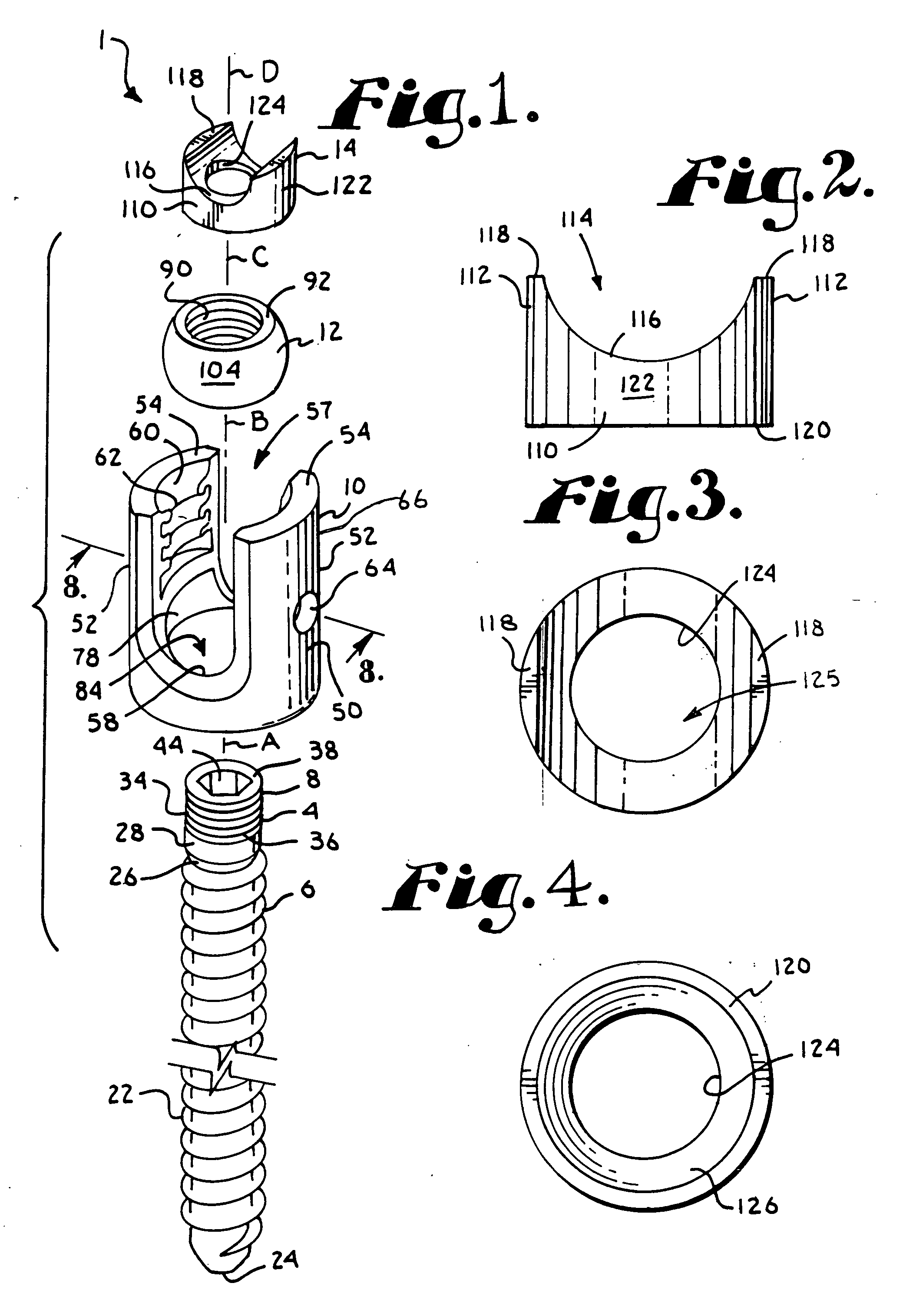
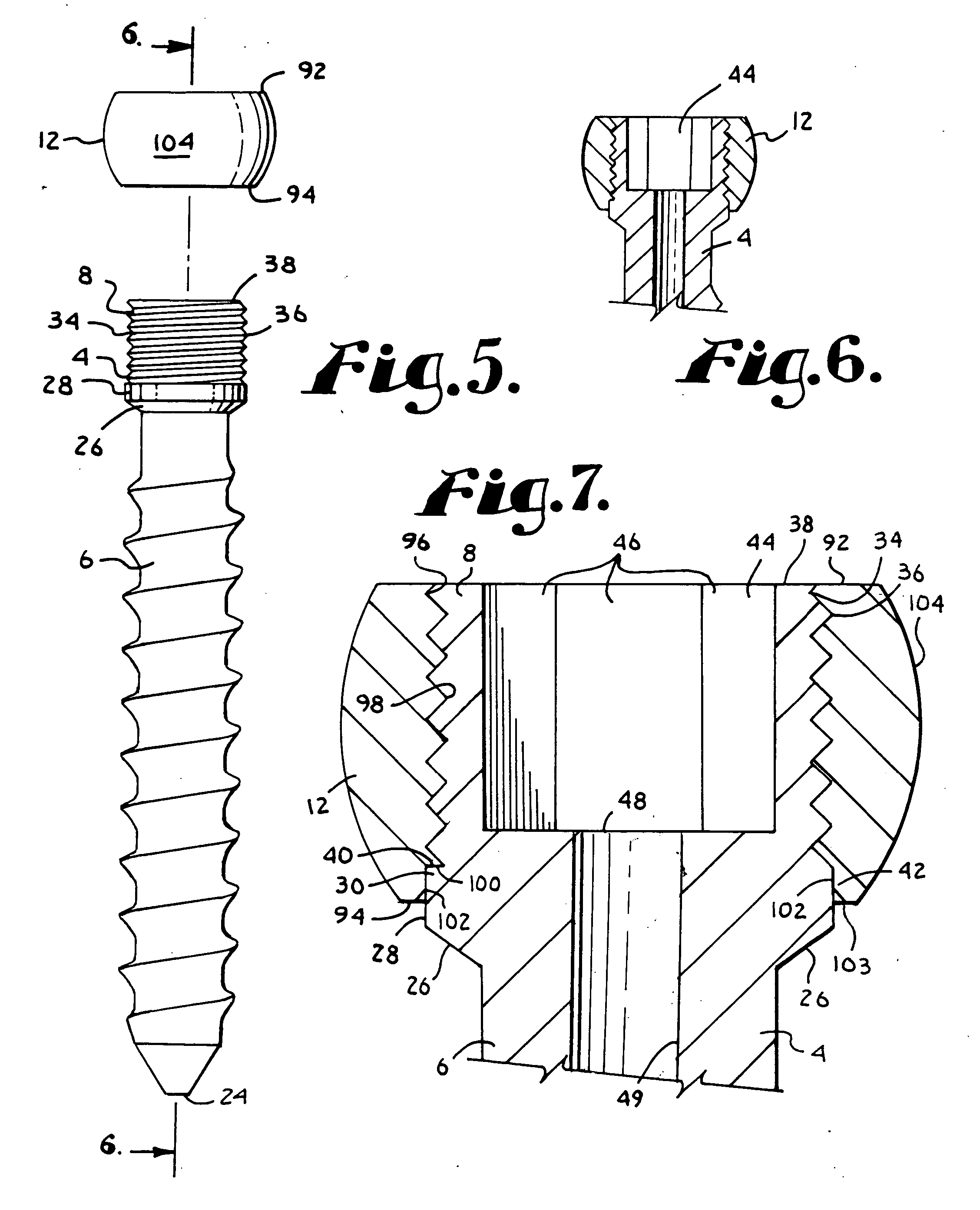
[0033] With reference to FIGS. 1-14, the reference numeral 1 generally designates a polyaxial bone screw assembly according to the present invention. The assembly 1 includes a shank 4 that further includes a body 6 integral with an upwardly extending, substantially cylindrical end or capture structure 8; a receiver or head 10; a retaining and articulating structure 12; and a compression structure 14. The shank 4, the receiver 10, the retaining and articulat...


PUM


Abstract

A polyaxial bone screw assembly includes a threaded shank body having an upper portion with a capture structure thereon, a retaining and articulating structure, a compression structure and a receiver for holding the capture structure, retaining and articulating structure, compression structure and a rod. The receiver includes arms that define a channel for receiving the rod. The arms have inner surfaces with a discontinuous flange form thereon for mating with a cooperating continuous flange form of a closure structure for capturing the rod within the receiver. The shank capture structure and the retaining and articulating structure are threadably attached and secured to one another with a buttress stop. In operation, the compression structure is disposed within the receiver between the shank upper portion and a rod but presses only upon the retaining and articulating structure. The retaining and articulating structure has an external substantially spherical surface that mates with an internal surface of the receiver, providing a ball joint, enabling the receiver to be disposed at numerous angles relative to the shank body. The shank upper portion includes a tool engagement formation for driving the shank body into bone.

Description

CROSS REFERENCE TO RELATED APPLICATIONS [0001] This application claims the benefit of U.S. Provisional Application No. 60 / 655,239 filed Feb. 22, 2005.BACKGROUND OF THE INVENTION [0002] The present invention is directed to polyaxial bone screws for use in bone surgery, particularly spinal surgery. [0003] Bone screws are utilized in many types of spinal surgery, such as for osteosynthesis, in order to secure various implants to vertebrae along the spinal column for the purpose of stabilizing and / or adjusting spinal alignment. Although both closed-ended and open-ended bone screws are known, open-ended screws are particularly well suited for connections to rods and connector arms, because such rods or arms do not need to be passed through a closed bore, but rather can be laid or urged onto the open receiver channel of an open ended bone screw. [0004] Typical open-ended bone screws include a threaded shank with a pair of parallel projecting branches or arms which form a yoke with a U-sha...

Claims


Application Information

Patent Timeline
IPC IPC(8): A61F2/30
CPCA61B17/7032A61B17/7037A61B2019/307A61B2090/037
Inventor JACKSON, ROGER P.
Owner JACKSON
Learn More