
Optical bus extension device

Inactive Publication Date: 2006-09-07
CUBIX CORP
View PDF11 Cites 23 Cited by
  • Summary
  • Abstract
  • Description
  • Claims
  • Application Information

AI Technical Summary

Benefits of technology

[0014] The various embodiments of the present invention may, but do not necessarily, achieve one or more of the following advantages:
[0025] provide a secure communication network that does not leave an electromagnetic signature.
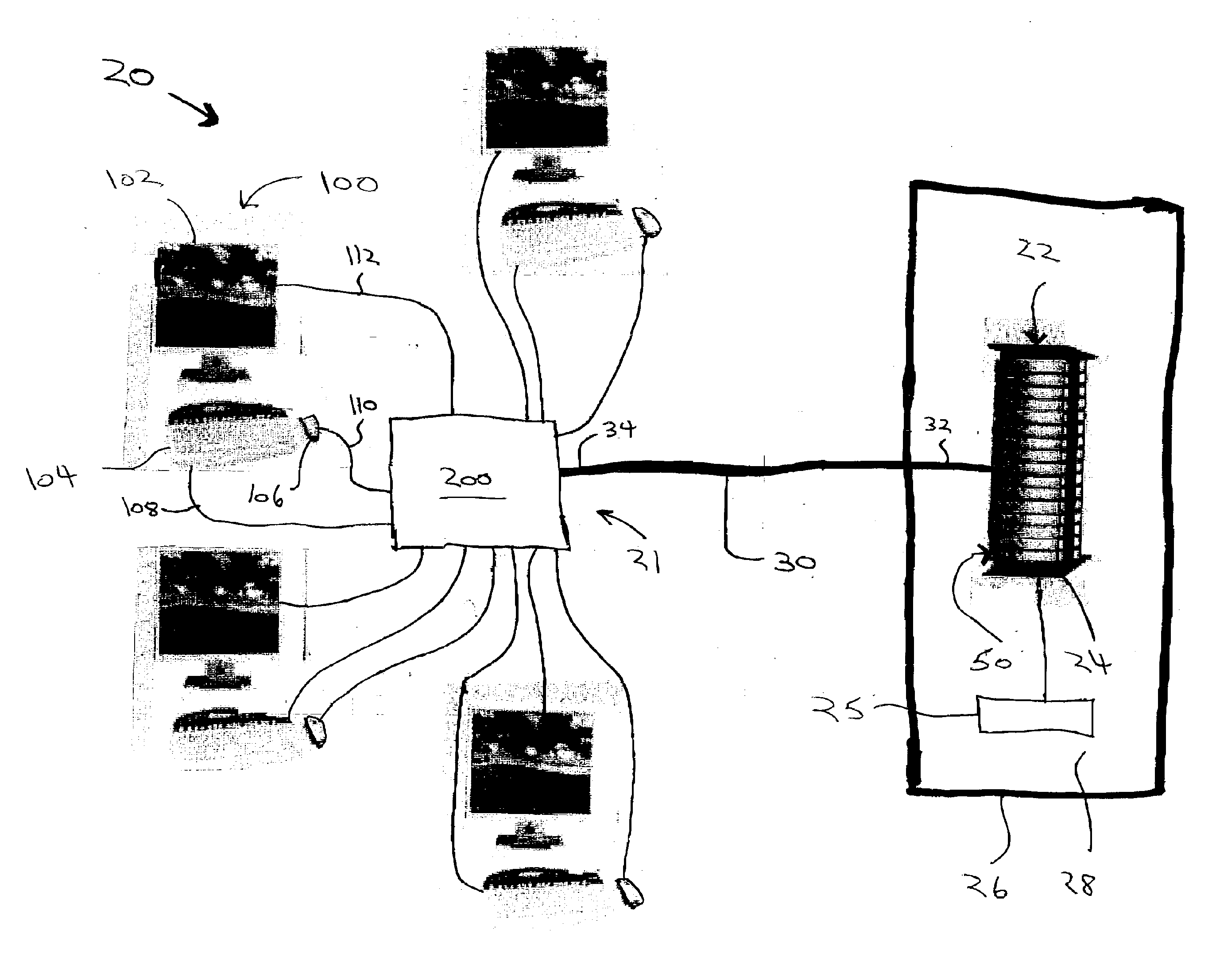
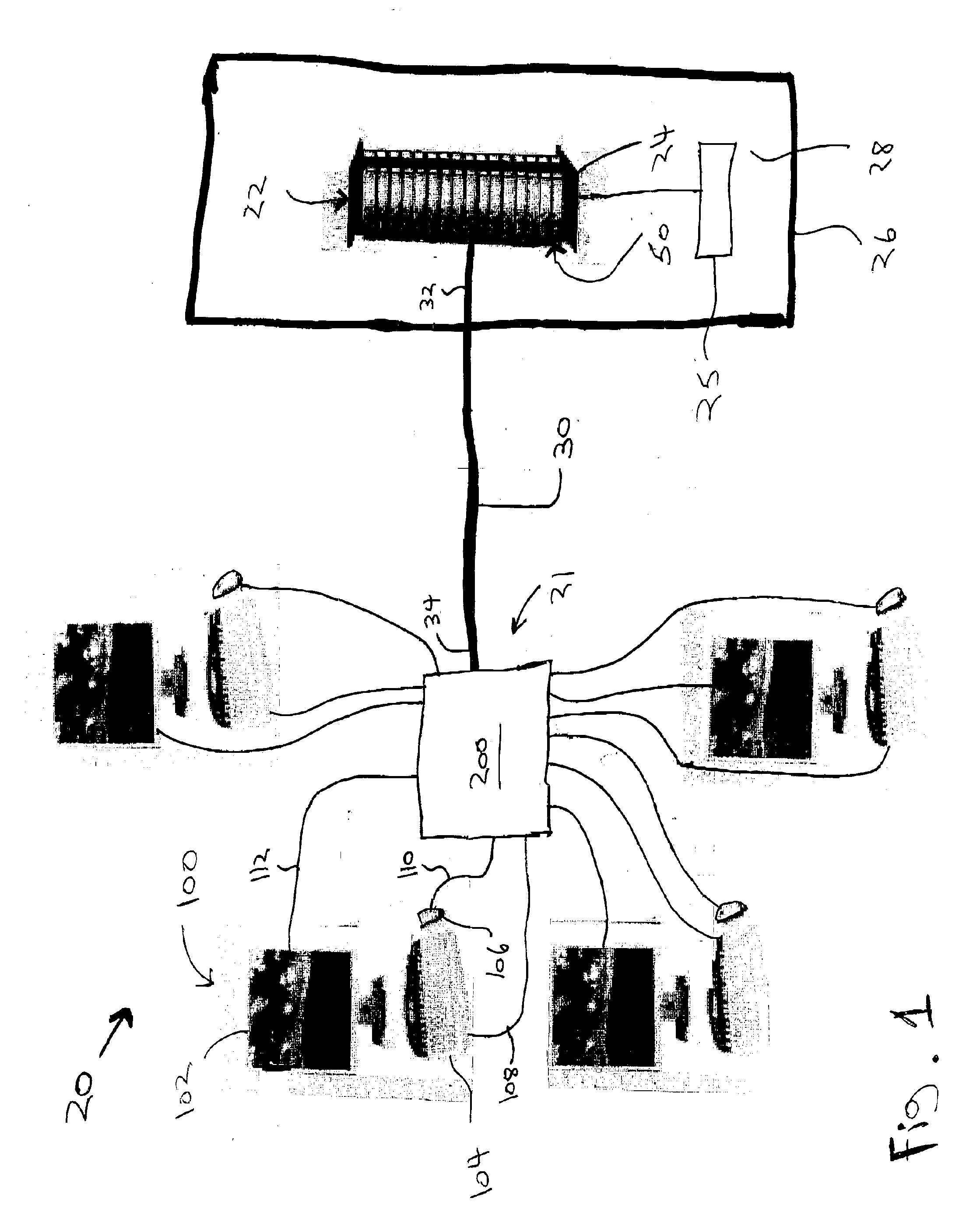
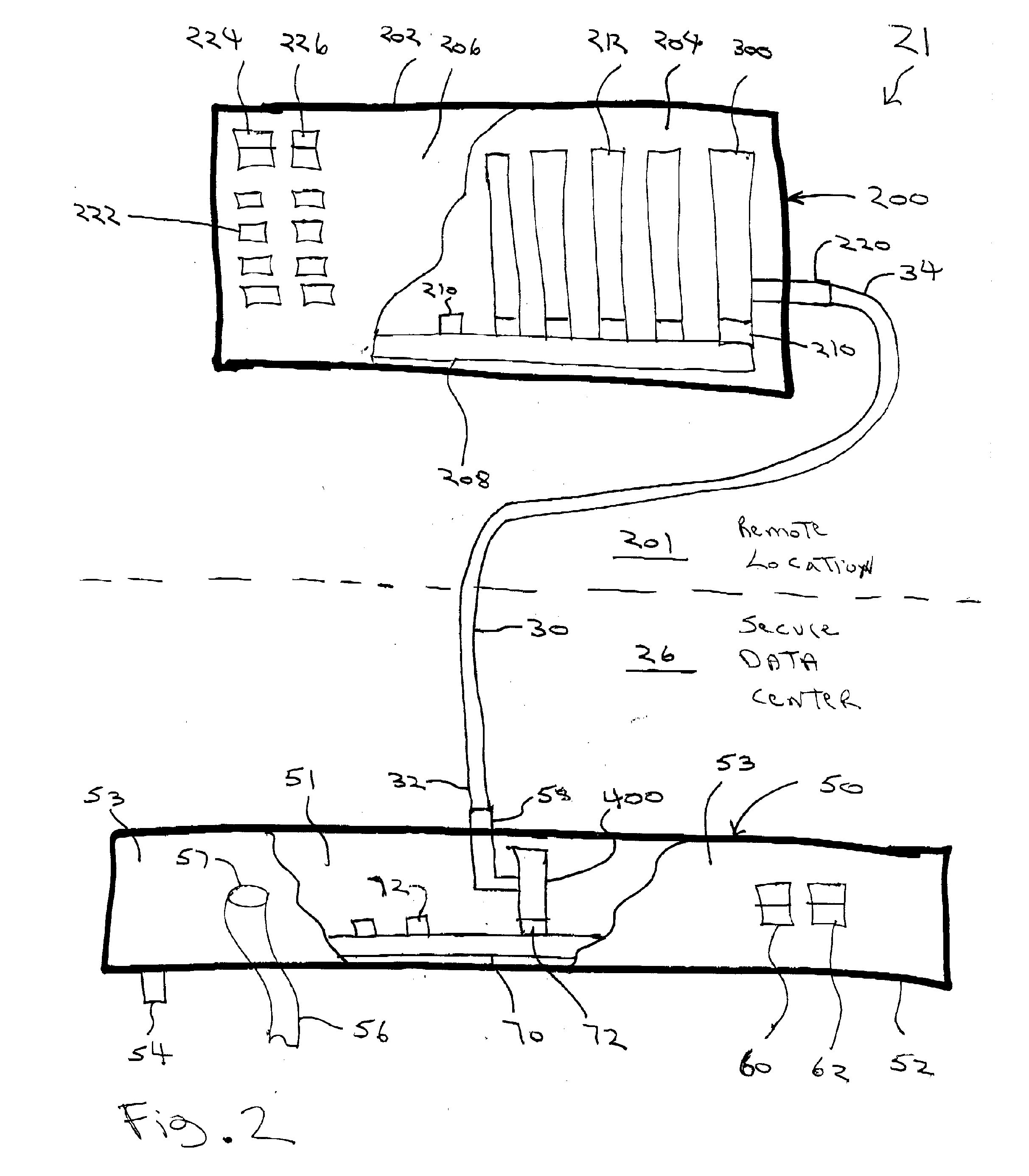
[0027] The present invention comprises a computer communication device that includes a first interface circuit mounted in association with a host computer. The first interface circuit is connected between a host computer bus and a first fiber optic transceiver. The first fiber optic transceiver can be connected with a fiber optic cable. A second interface circuit is mounted remotely from the host computer. The second interface circuit is connected between a peripheral device bus and a second fiber optic transceiver. The second fiber optic transceiver can be connected with the fiber optic cable. The computer communication device allows a peripheral device to be located remote from the host computer.

Problems solved by technology

Unfortunately, in networks of personal computers, computer maintenance, data backup and security are difficult to implement.
Individual computers distributed throughout a building can be subject to theft and vandalism.
With each computer widely spaced, repairs by a technician can be difficult and time consuming.
In a factory location, personal computers may be located in a harsh or dirty environment that may cause the computers to fail.
Another problem associated with traditional computers is data security due to radiated electromagnetic emissions.

Method used


Image

  • Optical bus extension device
  • Optical bus extension device
  • Optical bus extension device

Examples


Embodiment Construction

[0063] In the following detailed description of the embodiments, reference is made to the accompanying drawings, which form a part of this application. The drawings show, by way of illustration, specific embodiments in which the invention may be practiced. It is to be understood that other embodiments may be utilized and structural changes may be made without departing from the scope of the present invention.

[0064] Computer System

[0065] The present invention comprises a computer system or assembly, generally indicated by reference number 20. Referring to FIG. 1, computer system 20 can include a communication device 21 that provides communications between a host computer 50 and one or more peripheral devices 100. A group or network 22 of host computers 50 are mounted in a rack 24. Rack 24 can be conventional computer rack and include a housing, power cables, and cooling fans. Computers 50 can be conventional personal computers that are based upon microprocessor architecture and inc...


PUM


Abstract

The present invention comprises a computer communication device that includes an interface circuit mounted with a computer. The interface circuit is connected between a computer bus and fiber optic transceiver. Another interface circuit is mounted remotely from the computer. The other interface circuit is connected between a peripheral device bus and another fiber optic transceiver. Both fiber optic transceivers can be connected to opposite ends of a fiber optic cable. The computer communication device allows a peripheral device to be located remote from the computer.

Description

CROSS REFERENCE TO RELATED APPLICATIONS [0001] This application claims priority to U.S. provisional patent application Ser. No. 60 / 643,185, filed Jan. 12, 2005 and entitled, “Optical Bus Extension,” the contents of which are herein incorporated by reference.BACKGROUND [0002] 1. Field of the Invention [0003] The present invention relates to a computer communication device that is used to interface a host computer to remote peripheral devices. In particular, the invention relates to a device that connects remote peripheral devices on a PCI bus through a fiber optic connection to a host computer PCI express bus. [0004] 2. Description of the Related Art [0005] Personal computers are in widespread use through out offices, schools and corporations. An individual personal computer is typically located at each user location. Each computer is typically linked to a network by a communication device such as an Ethernet card and category 5 cabling. [0006] Unfortunately, in networks of personal ...

Claims


Application Information

Patent Timeline
IPC IPC(8): G06F13/38
CPCG06F13/385
Inventor GROSO, JOSEPH
Owner CUBIX CORP
Learn More