
Velocity estimator for manipulators and musical instrument using the same

a technology of velocity estimator and manipulator, which is applied in the direction of instruments, electrophonic musical instruments, measurement devices, etc., can solve the problems of poor artistic expression fidelity, the controller cannot directly control the velocity of the hammer after, etc., and achieve high fidelity

Active Publication Date: 2006-09-14
YAMAHA CORP
View PDF1 Cites 11 Cited by
  • Summary
  • Abstract
  • Description
  • Claims
  • Application Information

AI Technical Summary

Benefits of technology

[0007] It is therefore an important object of the present invention to provide an estimator, which makes a hybrid musical instrument reenact a performance at high fidelity.

Problems solved by technology

As known to persons skilled in the art, the hammer start the free rotation at the escape of the jacks of the action units, which are actuated with the keys, so that the controller can not directly control the hammer velocity after the escape.
A problem inherent in the prior art is the poor fidelity in the artistic expression.

Method used


Image

  • Velocity estimator for manipulators and musical instrument using the same
  • Velocity estimator for manipulators and musical instrument using the same
  • Velocity estimator for manipulators and musical instrument using the same

Examples


first embodiment

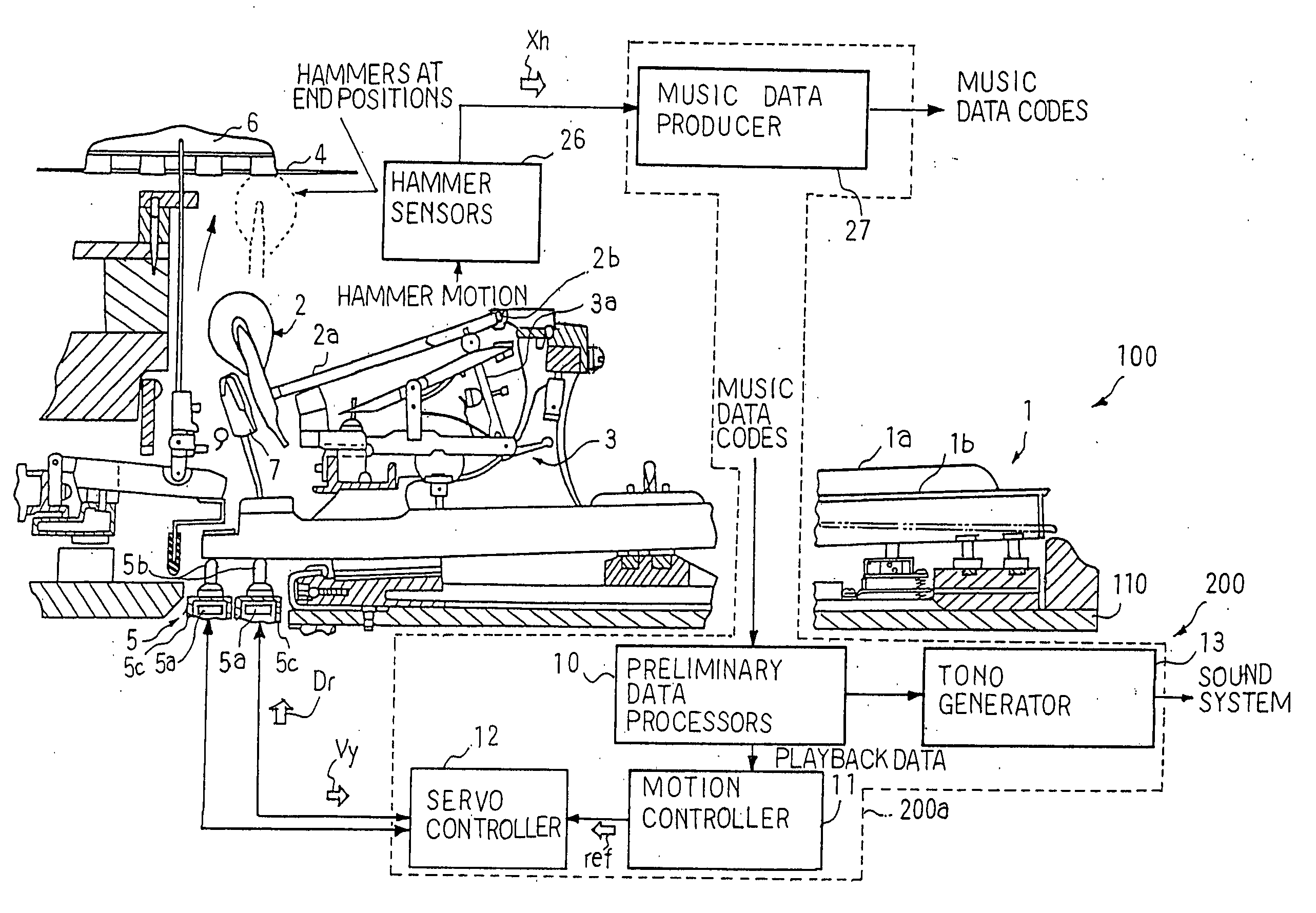
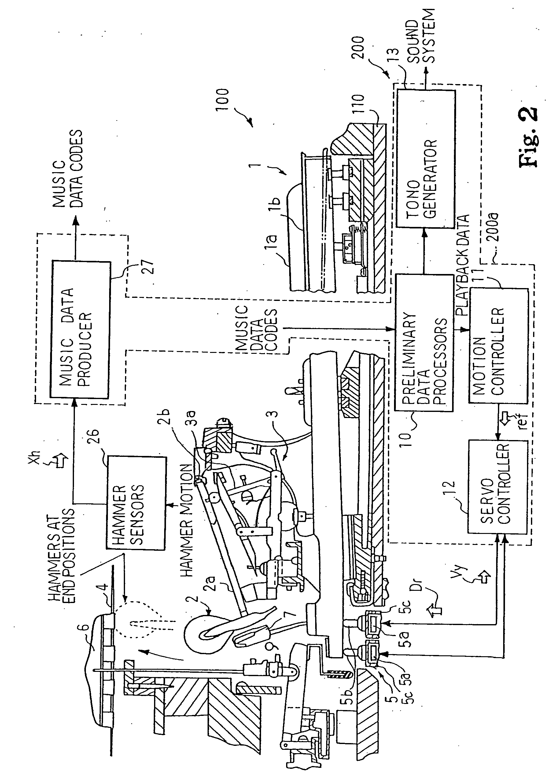
[0036] Referring to FIG. 2 of the drawings, an automatic player piano embodying the present invention largely comprises an acoustic piano 100 and an electronic system 200. The electronic system 200 is installed in the acoustic piano 100, and serves as at least a recorder and an automatic player. A user is assumed to instruct the recorder to record his or her performance. While the user is playing a piece of music on the acoustic piano 100, the recorder analyzes key motion and pedal motion for piano tones produced in the acoustic piano, and memorizes pieces of music data expressing the tones to be produced in music data codes. On the other hand, when the user instructs the automatic player to reenact the original performance, the automatic player starts to process the music data codes, and reproduces the key motion and pedal motion for the tones identical with those in the original performance.

[0037] As will be hereinlater described in detail, an estimator is incorporated in the rec...

second embodiment

[0091] Another automatic player piano embodying the present invention also comprises an acoustic piano and an electronic system. The acoustic piano is similar in structure to the acoustic piano 100, and the electronic system is identical in hardware with the electronic system 200. A computer program is same as the computer program installed in the controller 200a except for a subroutine program for the recording shown in FIG. 10. For this reason, description is focused on the estimation program, and component parts of the acoustic piano and system components of the electronic system are hereinafter labeled with the references designating the component parts of the acoustic piano 100 and the system components of the electronic system 200.

[0092] A user is assumed to instruct the electronic system to record his or her performance. While the user is fingering a piece of music on the acoustic piano, the main routine program periodically branches to the subroutine program for the recordi...


PUM


Abstract

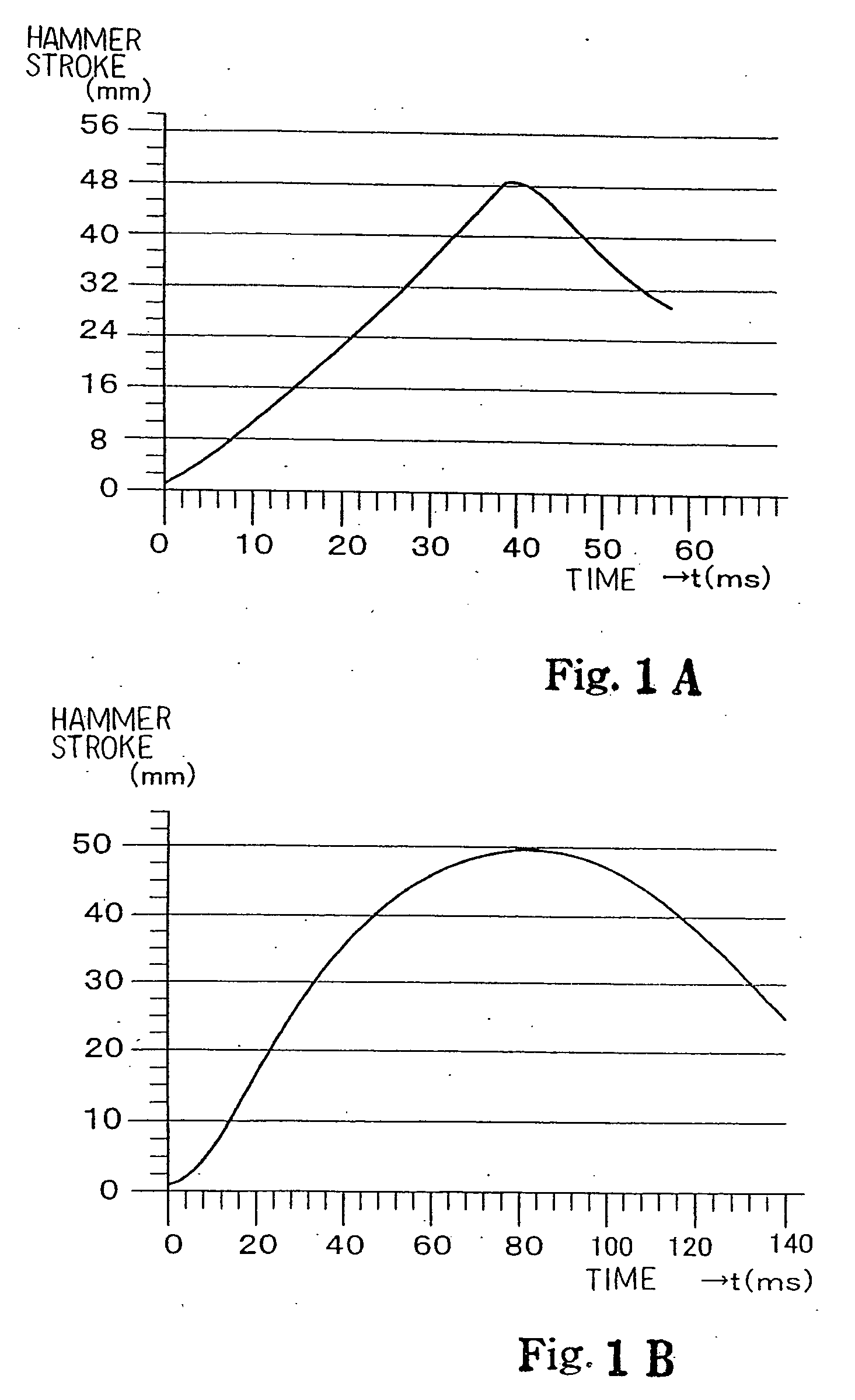
An automatic player piano is a combination between an acoustic piano and an electronic system serving as a recorder and an automatic player; while a user is fingering a piece of music on the acoustic piano, the player strongly depresses some keys and softly depresses other keys so as to give artistic expression to the tones, and the depressed keys give rise to hammer motion at different values of hammer velocity; since the hammer velocity is proportional to the loudness of tones, the controller is expected exactly to determine the hammer velocity; the hammers travel on linear trajectories and parabolic trajectories depending upon the hammer velocity so that the controller estimates the hammer velocity by using different methods, whereby the controller can produce music data codes exactly expressing the tones to be produced.

Description

FIELD OF THE INVENTION [0001] This invention relates to an estimator for a physical quantity expressing motion of a component part of a system and, more particularly, to a velocity estimator for estimating final velocity of manipulators such as, keys, and a musical instrument equipped with the velocity estimator. DESCRIPTION OF THE RELATED ART [0002] An automatic player piano is a typical example of the hybrid musical instrument. The automatic player piano is a combination of an acoustic piano and an electronic system, and users enjoy themselves recording and reproducing pieces of music by means of the electronic system. Sensors are required for the recording and playback through a servo control. [0003] A typical example of the hammer sensor is disclosed in Japanese Patent Application laid-open No. 2001-175262. The prior art hammer sensors continuously convert the stroke of the associated hammer to hammer position signals. The physical quantity, which expresses the hammer motion, is...

Claims


Application Information

Patent Timeline
IPC IPC(8): G10H1/02G10H7/00G01P3/00
CPCG10G3/04G10H1/344G10H2220/305
Inventor SASAKI, TSUTOMUFUJIWARA, YUJI
Owner YAMAHA CORP
Learn More