[0029] By providing downhole apparatus having a flow channel where at least one dimension of the channel is non-uniform, flow characteristics of a downhole medium flowing through the channel (such as velocity, pressure and
turbidity) may vary along the length of the channel. This may promote turbulent flow resulting in thorough mixing of constituents of the downhole medium, and / or scouring of surfaces of the channel to prevent adhesion of materials to the channel walls. This may thereby assist in preventing blockage of the channel by, for example, solids such as
drill cuttings, mud residues and the like present in the downhole medium. In preferred embodiments, the flow channel may define at least one
nozzle, restriction or the like tending to cause an increase in velocity of a downhole medium flowing through the channel, assisting in preventing blockage of the channel by solids in the medium, by jetting the medium through the channel. Furthermore, provision of restrictions of this type may assist clearing of any blockages that may occur, by creating a
piston-effect, in use. This is because any blockage will result in an increase in pressure of the medium behind the blockage, tending to urge the blocked solids through the restriction to clear the channel.
[0039] The apparatus may be adapted to be translated relative to the borehole / downhole tubing with the body in
sliding contact with the borehole / tubing wall. To facilitate this movement, the main axis of each rib, and thus of corresponding axes of the channels, may be disposed substantially parallel to a longitudinal axis of the body. Such an arrangement may reduce or avoid generation of a reaction torque in the body due to flow of downhole medium through the channel when the body is translated relative to the borehole / tubing.
[0040] Alternatively, the main axis of each rib and thus corresponding axes of the channels may be disposed non-parallel to a longitudinal axis of the body, that is, inclined relative to the
body axis. For example, in embodiments of the invention, the ribs may be helically oriented and thus may extend in a
helical direction around the body. This may be of particular utility where it is desired, for example, to promote turbulence in the downhole medium, which may facilitate cleaning and / or transportation of the medium, in particular any entrained solids, to surface.
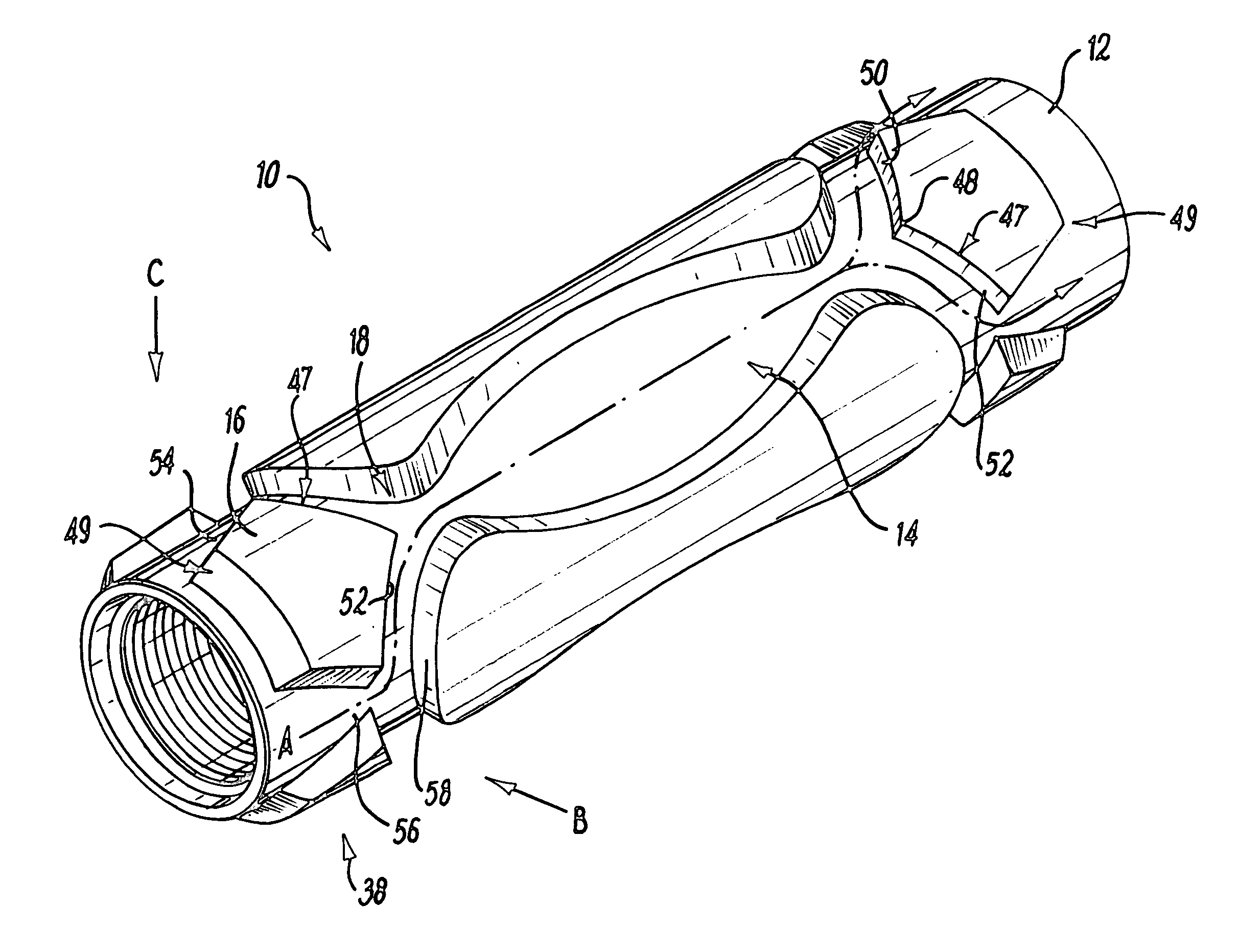
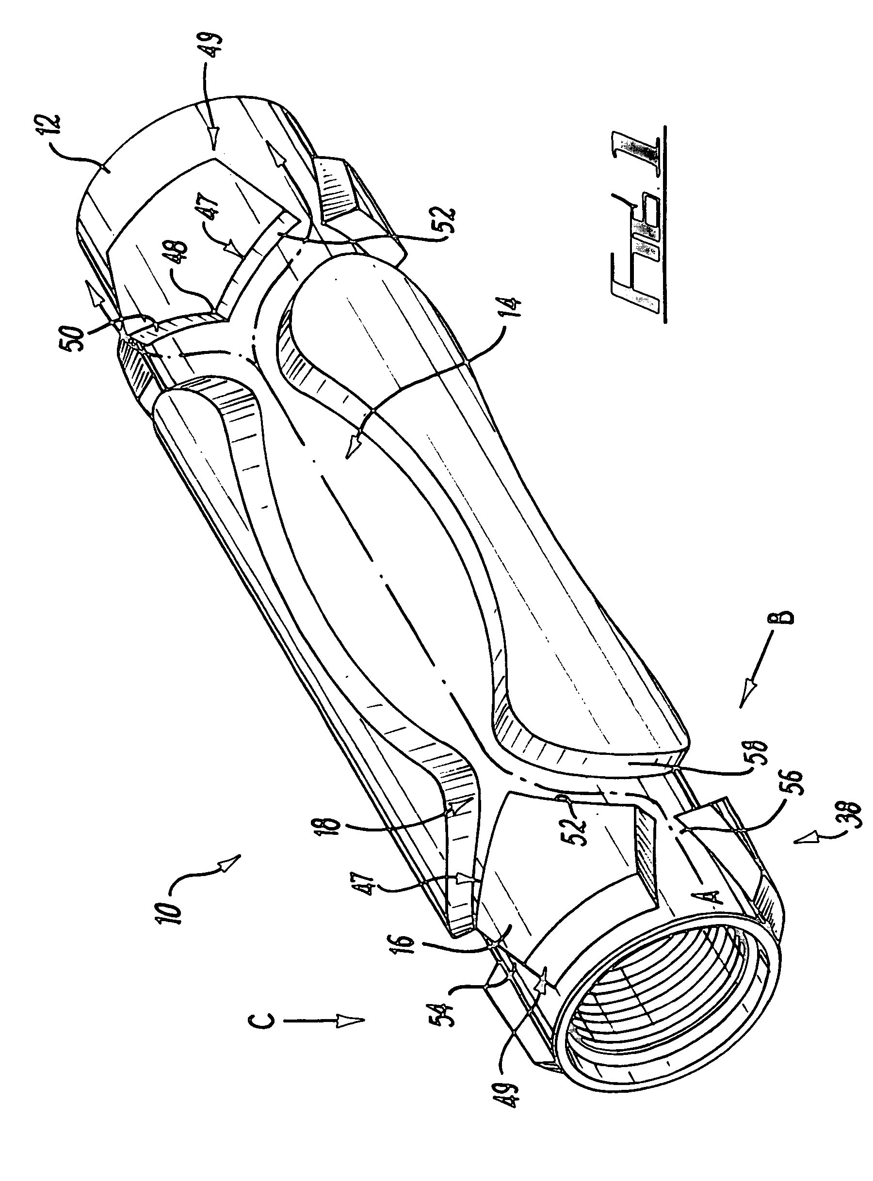
[0041] The channel may define a corresponding channel axis and the flow guide may be located on or parallel to the channel axis and may be spaced axially along the body relative to the channel. Preferably, the flow guide is located such that downhole medium flowing out of the channel impinges on the flow guide (which may assist in preventing blockage of the channel by breaking up and mixing the flow of the downhole medium and thus of the downhole medium constituents), and / or so as to direct downhole medium around the flow guide and into the channel. It will be understood that the flow guide directs the medium flowing away from or into the channel depending upon the direction of flow of fluid relative to the body.
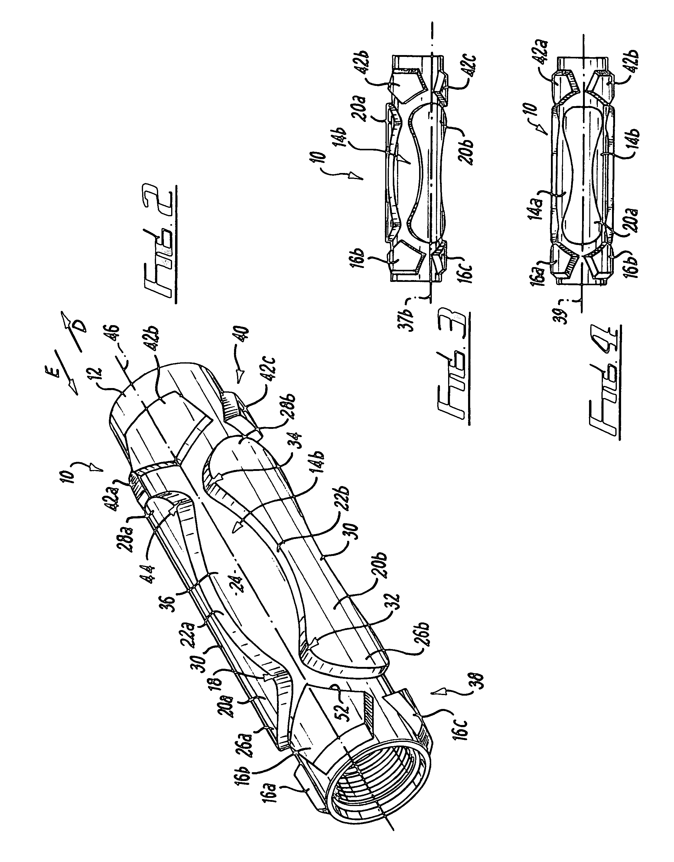
[0048] The ribs may define an outer surface adapted to abut an inner wall of a borehole or a tubing in which the apparatus is located, and a
diameter described by the ribs may thus be greater than an outer
diameter of the main body. The ribs may be shaped such that the ribs are adapted to abut said wall over a majority, for example, 75% or more, optionally 90% or more, of an internal circumference of the wall at a selected location or locations along the length thereof. This location may correspond to portions of the ribs of greater width. This may, in use, provide improved stability when compared to known apparatus such as prior centralisers / stabilisers. These locations may be spaced apart along the length of the ribs so as to optimise stability of the apparatus, in use. Furthermore, this arrangement of the ribs may facilitate flexing of the apparatus in use, the main body flexing in regions of the body where the ribs are of reduced width.
[0049] The apparatus may comprise a plurality of flow guides spaced around a circumference of the body, adjacent flow guides defining part of a flow path. Adjacent flow guides may define a circumferential opening therebetween, which may define an inlet and / or outlet of one or more flow path. The openings may be circumferentially spaced or staggered relative to axes of the channels. This may define a tortuous flow path for flow of the downhole medium around the flow guide and through the channel and thus across the body, improving mixing and reducing the likelihood of balling or adhesion of solids in the medium on the apparatus and in particular on the channel walls.

