
Apparatus for controlling a pressure control assembly in a hazardous area

Active Publication Date: 2006-09-14
MI
View PDF4 Cites 20 Cited by
  • Summary
  • Abstract
  • Description
  • Claims
  • Application Information

AI Technical Summary

Benefits of technology

[0005] Chokes positioned at the wellhead are often located in areas that are classified as hazardous. As such, the use of electric chokes may be limited to uses where they are not at the wellhead or in a hazardous area. It would be an improvement to have an electric choke that could be used at the wellhead or in other hazardous areas.
[0006] In one aspect, the present invention relates to an apparatus for controlling a choke assembly, wherein the choke assembly includes a housing having an inlet and an outlet in fluid communication with a wellbore, a fixed plate located between the inlet and the outlet and having an orifice therethrough for communicating fluid from the inlet to the outlet, a choke plate rotatably retained against the fixed plate and having an orifice therethrough, wherein the choke plate is rotatable to adjust a size of an orifice resulting from the relative positions of the orifice through the choke plate and the orifice through the fixed plate and is further rotatable to close the resulting orifice to prevent fluid communication therethrough. The apparatus may include an air source, an air purge system in fluid communication with the air source, a remote operating panel receiving data from at least one remotely located wellbore sensor, a local operating panel in electronic communication with the remote operating panel, and an actuator coupled to the assembly to control pressure within the wellbore. The remote operating panel may include an airtight housing in fluid communication with the air purge system, wherein air from the air purge system is circulated through the housing, a plurality of operator controls for manually controlling operation of the pressure control assembly, and a display for visually displaying values of data received from the wellbore sensor. The local operating panel may include an airtight panel housing in fluid communication with the air purge system, wherein air from the air purge system is circulated through the panel housing, and a local operator controller having an operator interface for receiving operator instruction input into the local panel, and operable to receive operator instructions from the remote panel and transmit operator instructions. The actuator may include a motor in an explosion-proof housing coupled to the choke plate and operable to adjust the orifice through the choke plate, wherein the motor receives electronic communication of the operator instructions transmitted by the local operator controller, and a position indicator coupled to the choke plate for sensing

Problems solved by technology

Similar potentially dangerous environmental conditions exist in locations in which petroleum products are being recovered, refined or processed.
Because electrical components, by their nature, may generate heat and sparks sufficient to ignite a flammable gas or other flammable mixture under even normal operating conditions, such components must be carefully selected and installed when used in an area that is classified as hazardous.
Chokes positioned at the wellhead are often located in areas that are classified as hazardous.
As such, the use of electric chokes may be limited to uses where they are not at the wellhead or in a hazardous area.

Method used


Image

  • Apparatus for controlling a pressure control assembly in a hazardous area
  • Apparatus for controlling a pressure control assembly in a hazardous area
  • Apparatus for controlling a pressure control assembly in a hazardous area

Examples


Embodiment Construction

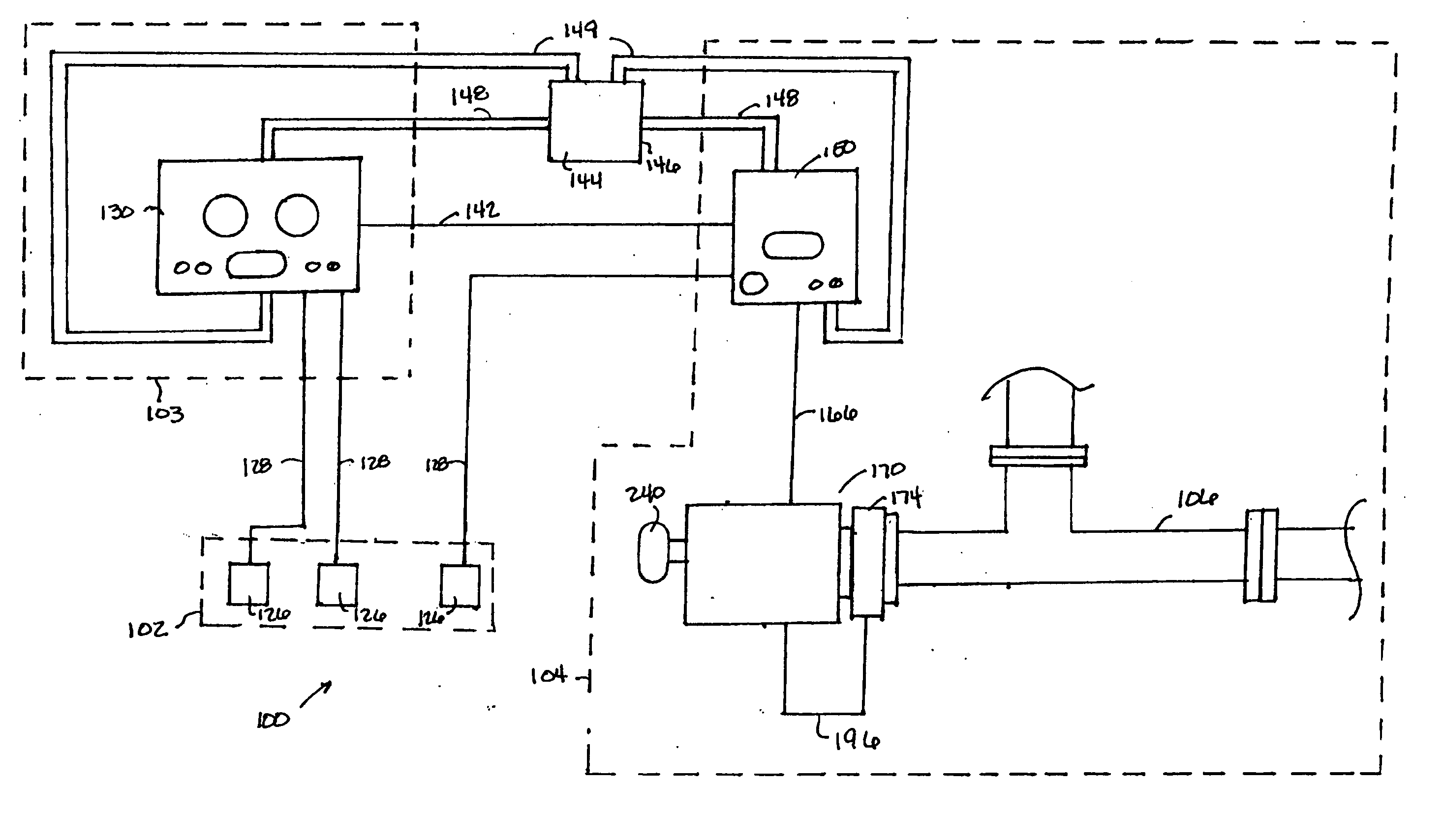
[0021] In one aspect, embodiments disclosed herein are directed to an apparatus for controlling a pressure control device. In another aspect, embodiments disclosed herein are directed to an apparatus for controlling a ;luality of pressure control devices. In yet another aspect, embodiments disclosed herein are directed to an apparatus for controlling pressure of a fluid in a wellbore. In each embodiment disclosed, the apparatus meets the requirements of Class 1, Division 1 standards as established by the American Petroleum Institute (API) and published in the API “Recommended Practice for Classification of Locations for Electrical Installations at Petroleum Facilities,” API Recommended Practice 500 (RP500), First Edition, Jun. 1, 1991, specifically incorporated herein by this reference.

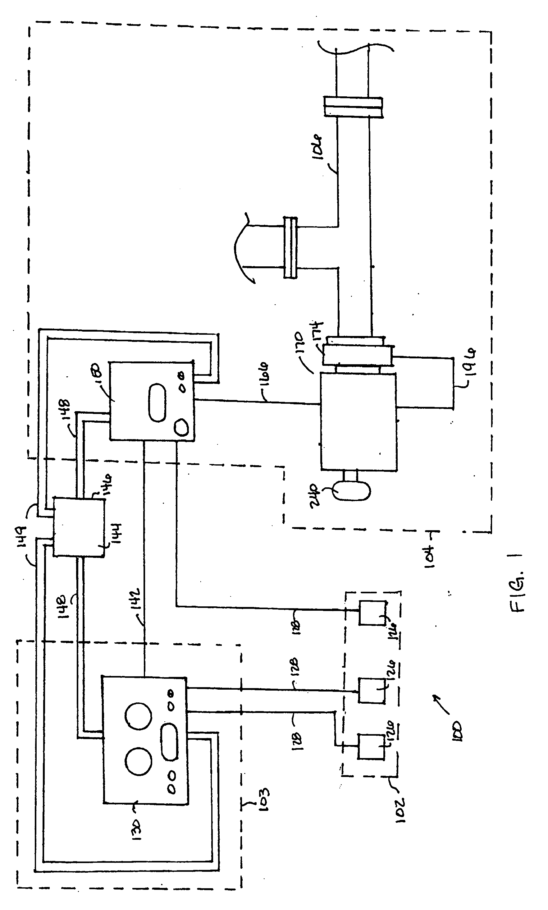
[0022] Referring to FIG. 1, an apparatus for controlling a pressure control device is shown generally as 100. The terms “pressure control device,”“pressure control assembly,” and “choke assembly” are...


PUM


Abstract

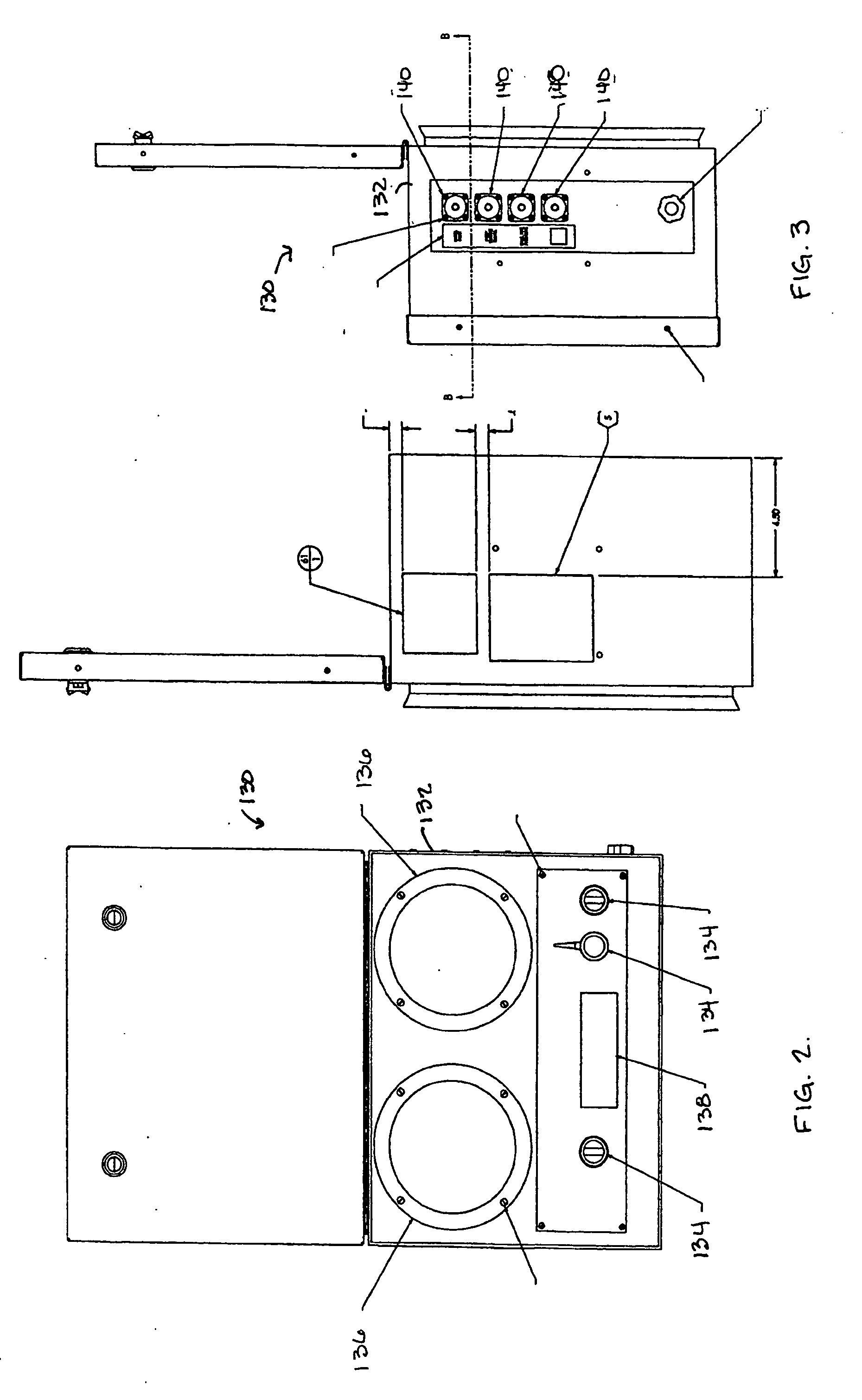
An apparatus operable is a hazardous area for controlling a choke assembly includes an air source, an air purge system in fluid communication with the air source, a remote operating panel receiving data from at least one remotely located wellbore sensor, a local operating panel in electronic communication with the remote operating panel, and an actuator coupled to the assembly to control pressure within the wellbore. The remote operating panel includes an airtight housing in fluid communication with the air purge system, wherein air from the air purge system is circulated through the housing, a plurality of operator controls for manually controlling operation of the pressure control assembly, and a display for visually displaying values of data received from the wellbore sensor. The local operating panel includes an airtight panel housing in fluid communication with the air purge system, wherein air from the air purge system is circulated through the panel housing, and a local operator controller having an operator interface for receiving operator instruction input into the local panel, and operable to receive operator instructions from the remote panel and transmit operator instructions. The actuator includes a motor in an explosion-proof housing coupled to the choke plate and operable to adjust the orifice through the choke plate, wherein the motor receives electronic communication of the operator instructions transmitted by the local operator controller, and a position indicator coupled to the choke plate for sensing the orifice opening and providing feedback of the choke plate position to the motor.

Description

[0001] This application claims priority to U.S. Provisional Patent Application Ser. No. 60 / 658,640 filed on Mar. 4, 2005 entitled, “Electric Control System for a Pressure Control Device in a Hazardous Area” incorporated herein by reference for all purposes.BACKGROUND OF INVENTION [0002] High pressure valves, or chokes, are often positioned at the wellhead to control flow. There are three main types of chokes: manual chokes, which require the user to be physically in the manifold and operate the choke by hand as the gas flows through; hydraulic chokes, which allow the user to operate the choke remotely from the drilling floor or doghouse; and electric chokes, which also allow the user to operate the choke remotely and are able to perform consistently in varying environmental conditions as well as add digital capabilities to the choke. [0003] At locations where oil or gas wells are being drilled, a number of flammable gases may be present, including mixtures of oxygen, methane, ethane...

Claims


Application Information

Patent Timeline
IPC IPC(8): E21B47/00
CPCE21B21/106
Inventor ROGERS, BRIANBURKHARD, ALAN
Owner MI
Learn More