
Apparatus and method for improving uniformity in electroplating

Active Publication Date: 2006-09-14
APPLIED MATERIALS INC
View PDF13 Cites 45 Cited by
  • Summary
  • Abstract
  • Description
  • Claims
  • Application Information

AI Technical Summary

Benefits of technology

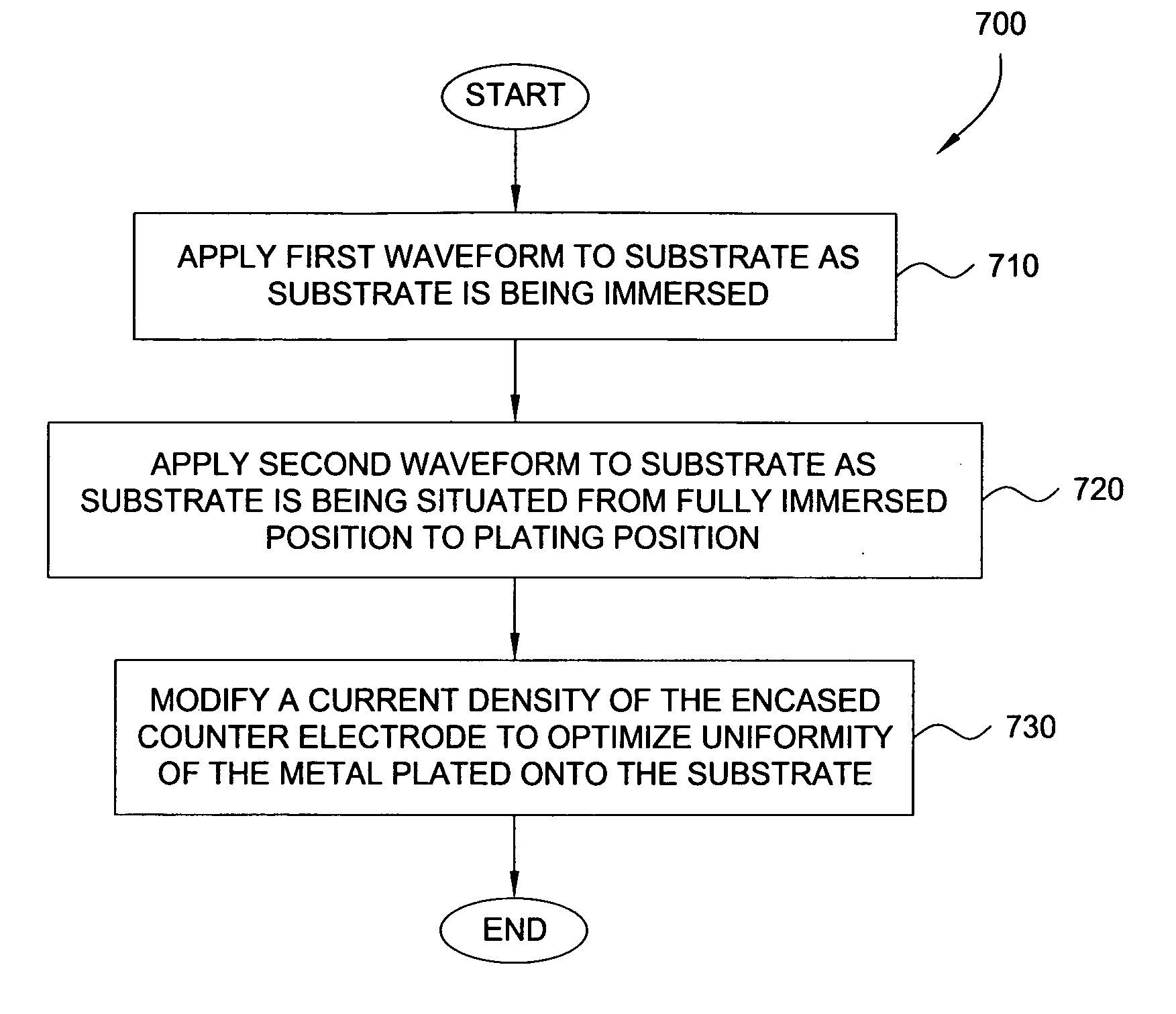
[0011] Embodiments of the present invention provide apparatus and method for minimizing terminal effect and adjusting plating profiles.

Problems solved by technology

However, electrochemical plating (ECP) of these features presents several challenges to conventional gap fill methods and apparatuses.
One such problem, for example, is that electrochemical plating processes generally require a conductive seed layer to be deposited onto the features to support the subsequent plating process.
The terminal effect results in a large difference in the plating rate across the substrate, leading to variations in film properties such as film composition and resistivity between the center and edge of the substrate.
More importantly, a highly non-uniform plating rate across the substrate during the filling of features forces the features at either the center or edge of the wafer to fill under sub-optimal conditions, resulting in problems, such as incomplete filling and trapped voids inside the features.
These configurations were only partly successful because of their lack of proximity to the perimeter of the substrate or inability to dynamically adjust the profile.

Method used


Image

  • Apparatus and method for improving uniformity in electroplating
  • Apparatus and method for improving uniformity in electroplating
  • Apparatus and method for improving uniformity in electroplating

Examples


Embodiment Construction

[0030] The present invention generally provides an electrochemical plating cell, with an encased auxiliary electrode assembly in fluid communication with the cathode compartment, configured to uniformly plate metal onto a substrate.

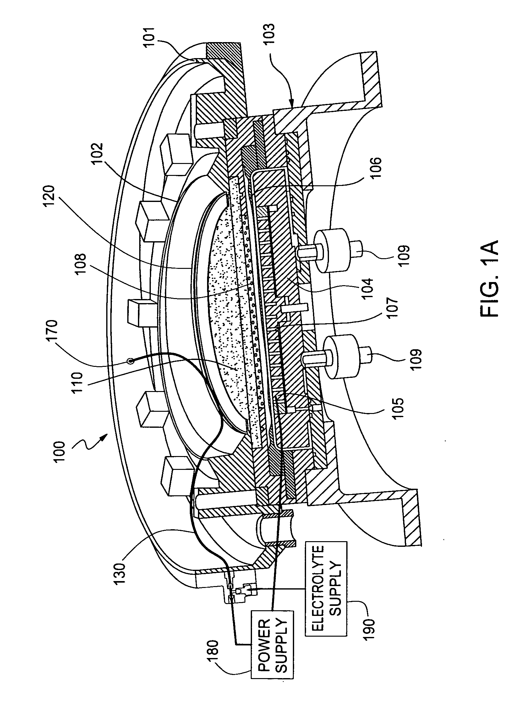
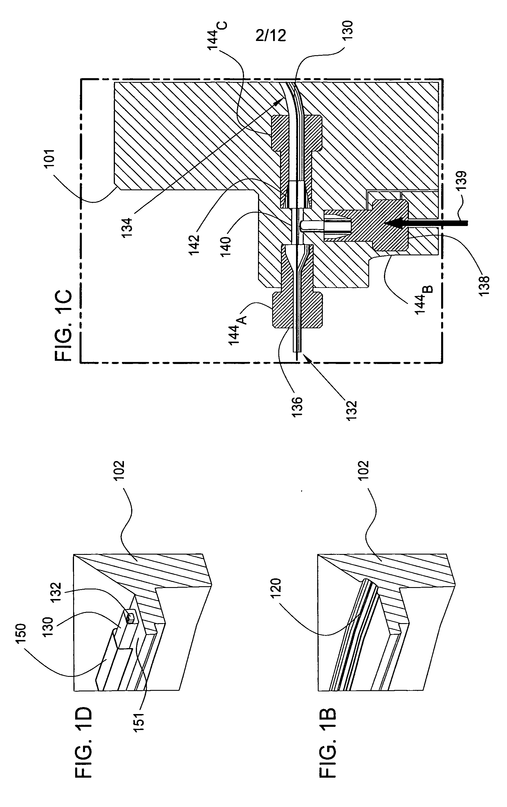
[0031]FIG. 1A illustrates a partial sectional perspective view of an exemplary electrochemical plating cell 100 containing an encased auxiliary electrode assembly 130 of the invention. The encased auxiliary electrode assembly 130 is composed of an auxiliary electrode 132 surrounded by electrolyte in a protective tube 134. In another embodiment, the electrolyte is absent and the protective tube is attached directly to the surface of the auxiliary electrode. The encased auxiliary electrode assembly 130 is generally configured to be used as a cathode when the substrate contacts (not shown) are configured as cathodes. Also, when configured as a cathode, the encased auxiliary electrode assembly 130 can be used (when the substrate contacts are configured as an...


PUM

PropertyMeasurementUnit
Fractionaaaaaaaaaa
Fractionaaaaaaaaaa
Fractionaaaaaaaaaa

Abstract

A method and apparatus for plating a metal onto a substrate. One embodiment of the present invention provides an apparatus for electroplating a substrate. The apparatus comprises a fluid basin, an anode disposed near a bottom of the fluid basin, a restrictor disposed above the anode, and a substrate support member configured to move the substrate within the fluid basin among different elevations relative to the restrictor. Plating profiles on the substrate may be adjusted by changing the elevation of the substrate during plating.

Description

CROSS-REFERENCE TO RELATED APPLICATIONS [0001] This application claims benefit of U.S. Provisional Patent Application Ser. No. 60 / 656,161 filed Feb. 25, 2005 and U.S. Provisional Patent Application Ser. No. 60 / 687,404 filed Jun. 3, 2005, which are herein incorporated by reference.BACKGROUND OF THE INVENTION [0002] 1. Field of the Invention [0003] Embodiments of the invention generally relate to methods and apparatus for electrochemical processing. One embodiment of the invention relates to an electrochemical processing cell configured to have an electric field with different profiles at different locations. [0004] 2. Description of the Related Art [0005] Metallization of high aspect ratio 90 nm and smaller sized features is a foundational technology for future generations of integrated circuit manufacturing processes. Metallization of these features is generally accomplished via an electrochemical plating process. In a typical process scheme, a metal, such as copper, is plated onto ...

Claims


Application Information

Patent Timeline
IPC IPC(8): C25D5/18
CPCC25D5/04C25D5/18C25D17/02C25D17/10H01L21/2885C25D7/123C25D17/001C25D17/002C25D17/007
Inventor HAFEZI, HOOMANROSENFELD, ARON
Owner APPLIED MATERIALS INC
Learn More