
Fluid-filled vibration damping device

a technology of vibration damping device and filling, which is applied in the direction of shock absorbers, machine supports, mechanical equipment, etc., can solve the problems of irregular deformation, insufficient seal performance in the area where the partition member and the rubber elastic film are attached, and difficulty in obtaining the desired vibration damping characteristics, etc., to reduce or eliminate and reduce the occurrence of high stress and strain in the tubular fitting member. ,

Active Publication Date: 2006-09-14
SUMITOMO RIKO CO LTD
View PDF5 Cites 13 Cited by
  • Summary
  • Abstract
  • Description
  • Claims
  • Application Information

AI Technical Summary

Benefits of technology

[0011] It is therefore one object of this invention to provide a a fluid-filled type vibration damping device of novel construction, whereby the desired vibration damping characteristics are consistently obtained, by means of ensuring adequate sealing performance in the area of attachment of the partition rubber film with the orifice member and partition member.

Problems solved by technology

However, numerous experiments and extensive studies carried out by the inventors have revealed that, in the fluid-filled type vibration damping devices taught in JP-U-5-77642 and JP-A-11-264436 cited previously, seal performance in the area where the partition member and the rubber elastic film are attached is not yet sufficiently consistent and reliable.
That is, since the shape and wall thickness dimension of the partition member are not uniform in the circumferential direction due to factors such as the shape and size of the orifice passage formed in the partition member, when in association with the drawing process compressive force is exerted by the second mounting member on the partition member, and on the tubular fitting member, irregular deformation tends to be produced in the partition member and the tubular fitting member, and the outer circumferential surface of the partition member abuts tightly against the seal rubber layer formed covering the inner circumferential surface of the second mounting member.
As a result, a gap tends to form between the rubber elastic film and the partition member, through which gap air escaping from the working air chamber can become entrained in the fluid, or the orifice passage can become short circuited, making it difficult to obtain the desired vibration damping characteristics.

Method used


Image

  • Fluid-filled vibration damping device
  • Fluid-filled vibration damping device
  • Fluid-filled vibration damping device

Examples


Embodiment Construction

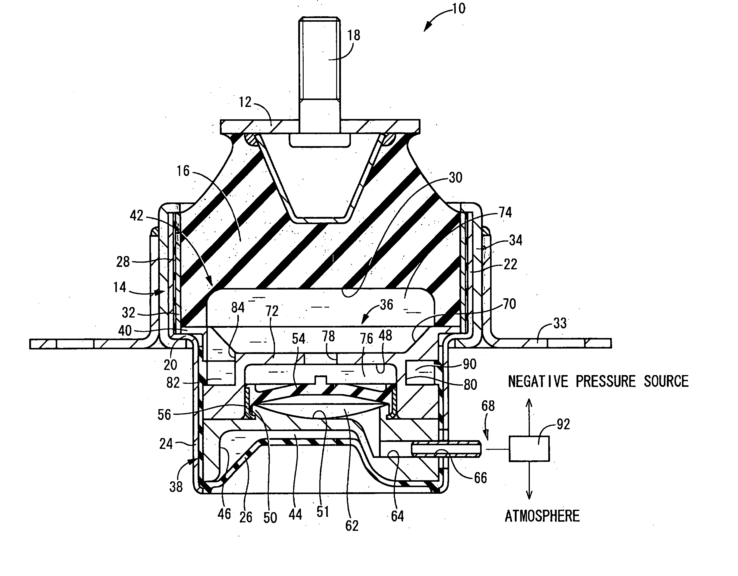
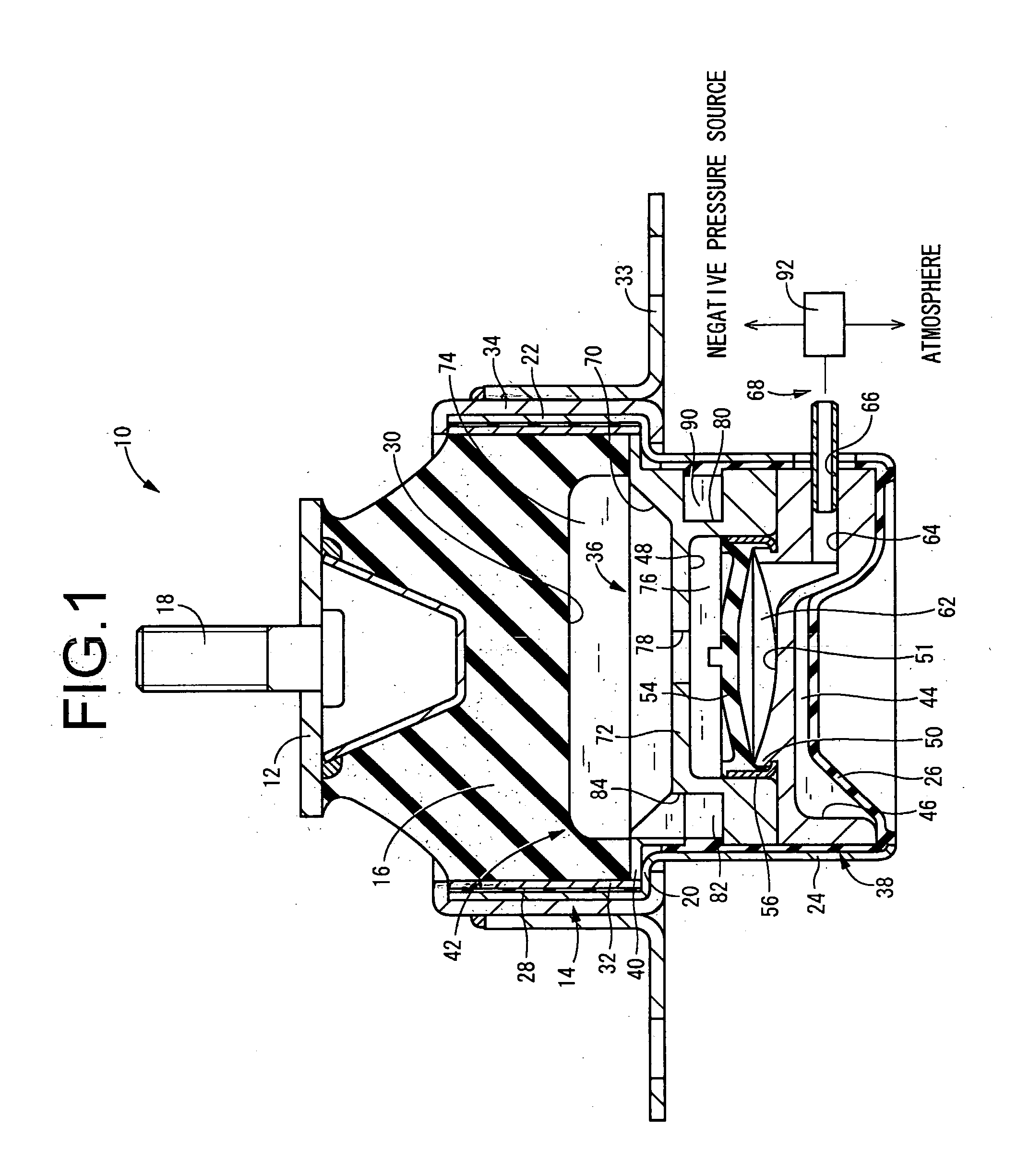
[0042] Referring first to FIG. 1, there is shown an automotive engine mount 10 as a first embodiment of the invention. The engine mount 10 is constructed of a first mounting member 12 of metal and a second mounting member 14 of metal, elastically connected together by a main rubber elastic body 16. The engine mount 10, in cooperation with another engine mount not shown in the drawings, supports the power unit on the body in a vibration damped manner, by means of attaching the first mounting member 12 to the power unit side and the second mounting member 14 to the body side. In the installed state, the engine mount 10, in association with elastic deformation of the main rubber elastic body 16 due to input of the distributed load of the power unit, undergoes relative displacement of the first mounting member 12 and the second mounting member 14 so that these move closer to one another a certain amount in the vertical direction; and the principal vibration to be damped is input across ...


PUM


Abstract

A fluid-filled type vibration damping device including: a primary fluid chamber partially constituted by a main rubber elastic body connecting a first and second mounting member; an equilibrium chamber partially constituted by a flexible film; a partition member supported by the second mounting member; and a partition rubber film is superimposed against the partition member and secured interlocking with an annular interlocking projection projecting from the partition member. A first seal rubber is compressed between the interlocking projection and the tubular fitting member and extending about the entire circumference, thereby forming a working air chamber therebetween. A gap is furnished between and a second seal rubber is compressed between the tubular fitting member and the orifice member, and extending about the entire circumference.

Description

INCORPORATED BY REFERENCE [0001] The disclosure of Japanese Patent Application No. 2005-071810 filed on Mar. 14, 2005 including the specification, drawings and abstract is incorporated herein by reference in its entirety. BACKGROUND OF THE INVENTION [0002] 1. Field of the Invention [0003] The present invention generally relates to a fluid-filled type vibration damping device that exhibits vibration-damping effect based on fluid action of a non-compressible fluid sealed within its interior, and more particularly to a fluid-filled type vibration damping device wherein a partition member, which partitions a primary fluid chamber and an equilibrium chamber both having the non-compressible fluid sealed therein, having a partition rubber film disposed therein so that the partition rubber film partially define the pressure receiving chamber; and wherein an air chamber is formed for restricting or allowing deformation of the partition rubber film. [0004] 2. Description of the Related Art [0...

Claims


Application Information

Patent Timeline
IPC IPC(8): F16F15/00F16F13/00
CPCF16F13/105F16F13/264
Inventor MAENO, HAJIMEMURAMATSU, ATSUSHIKOYAMA, HIRONORI
Owner SUMITOMO RIKO CO LTD
Learn More