Anti-rotation quick connector

a quick connector and anti-rotation technology, applied in the direction of pipe couplings, couplings, packaging, etc., can solve the problems of increasing machining time, reducing and affecting the service life of the connector

Inactive Publication Date: 2006-09-14
TI GRP AUTOMOTIVE SYST LLC
View PDF23 Cites 18 Cited by
  • Summary
  • Abstract
  • Description
  • Claims
  • Application Information

AI Technical Summary

Problems solved by technology

This relative rotational motion may be undesirable in certain applications.
Altering thread sizes for each port is costly because it makes uncommon tooling, adds material for the larger thread sizes, increases machining time and decreases batch size

Method used


Image

  • Anti-rotation quick connector
  • Anti-rotation quick connector
  • Anti-rotation quick connector

Examples


Embodiment Construction

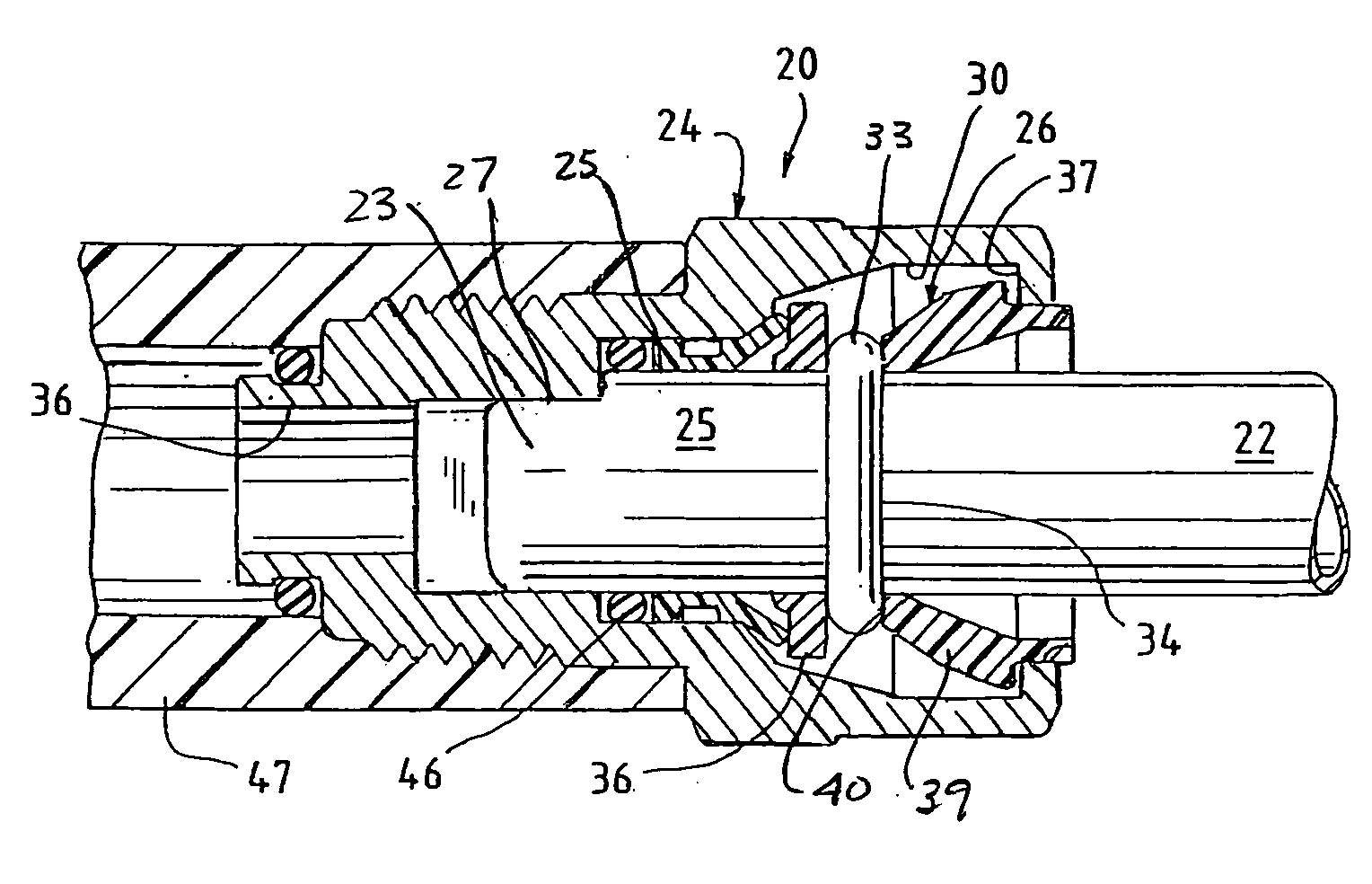
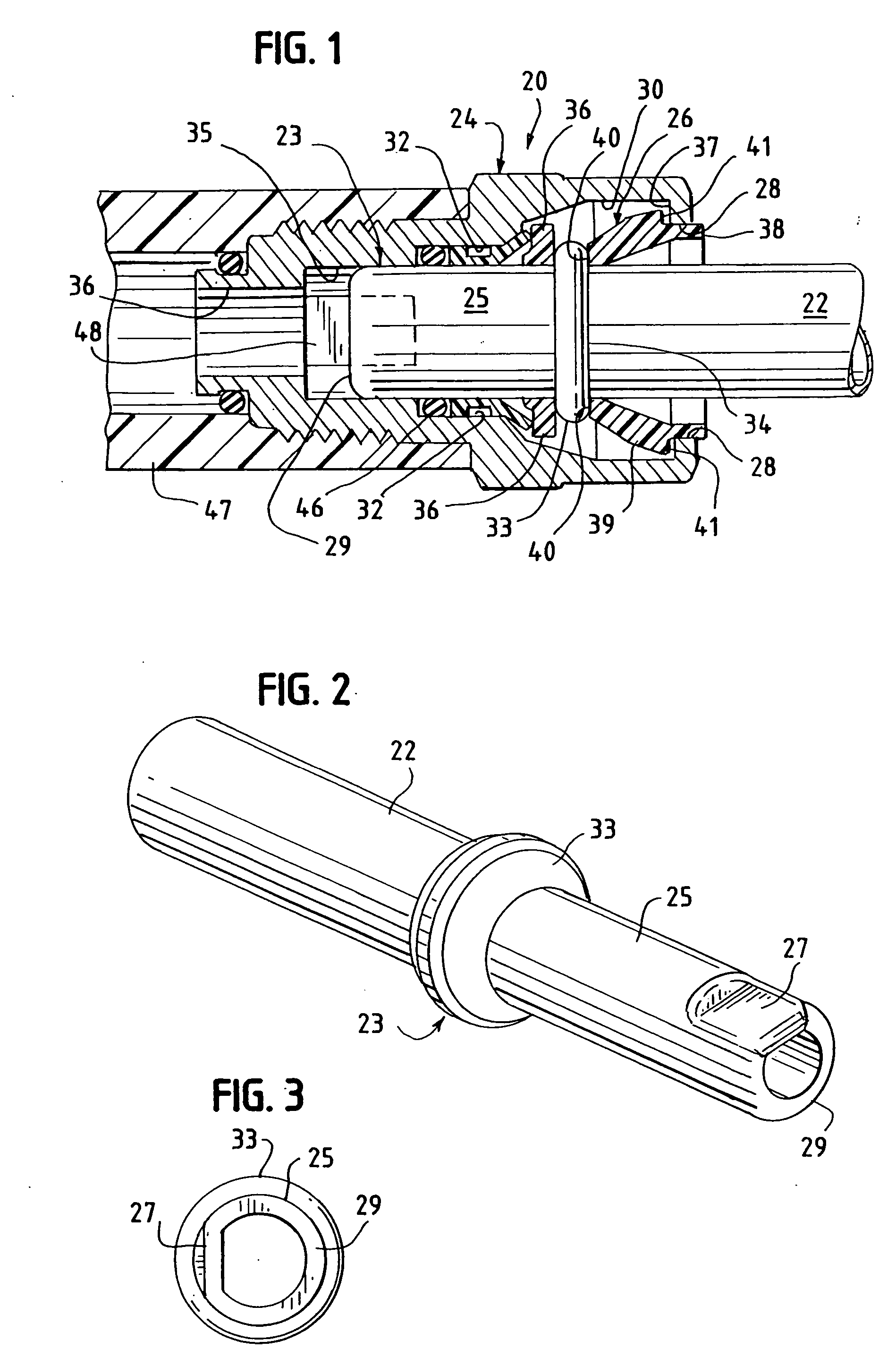
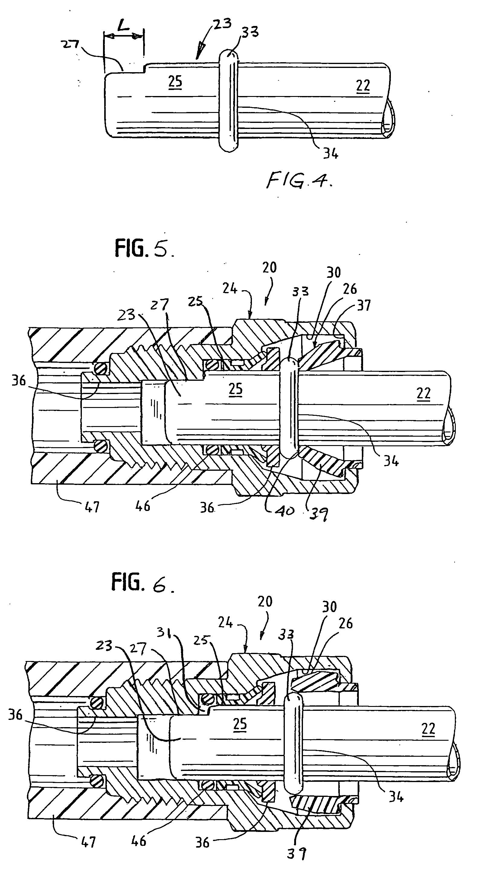
[0033]FIG. 1 illustrates a quick connector coupling assembly generally designated 20, embodying the principles of the present invention. It includes a fluid tube 22 and a body or housing 24. A retainer 26 provides a releasable connection between the tube 22 of a fluid system and the body 24. The body 24 is illustrated as connected to a flexible hose 47 that represents connection to the remainder of the fluid system. This connector coupling is generally similar to the quick connector disclosed in U.S. Pat. No. 5,161,832 the disclosure of which is hereby incorporated by reference herein.

[0034] The invention is suitable to be employed with numerous quick connector coupling arrangements. U.S. Pat. Nos. 5,257,833; 5,324,082; 5,395,140; 5,449,848; 5,628,531; and 6,086,118 are examples of quick connector couplings suitable for employing the invention. It is contemplated that the invention could be employed with numerous other known quick connector coupling arrangements as well.

[0035] Tub...


PUM


Abstract

A quick connector coupling assembly comprising a body, a tube, and a retainer to secure the tube in the body. The body defines an internal cavity extending from an opening. The tube has an endform extending through the opening and into the internal cavity. The endform has a tip and an engagement surface. The engagement surface of the endform coacts with a locking surface associated with the body or the retainer to resist rotational movement of the tube relative to the body.

Description

[0001] This application claims the benefits of U.S. Provisional Application No. 60 / 657,996, filed on Mar. 1, 2005. This invention relates to quick connectors to releasably secure a metal tube in a fluid system. More particularly, it relates to quick connectors that resist rotation of the connected tube.BACKGROUND OF THE INVENTION [0002] Quick connectors are used to assemble rigid fluid lines or tubes to mating components such as flexible hose, or a fluid system. The quick connector assembly includes some form of body or housing that defines an open receptacle with internal cylindrical surfaces of varying diameter that coact with the inserted tube. [0003] The tube has a free end portion that mates with the connector body receptacle. A retainer releasably couples the other two components together. [0004] All quick connector endforms allow rotation of the tube relative to the quick connector body. This relative rotational motion may be undesirable in certain applications. With a non-ro...

Claims


Application Information

Patent Timeline
IPC IPC(8): F16L37/00
CPCF16L37/088F16L2201/10F16L37/144F16L37/0987F16L37/0885B65D51/24B65D85/00
Inventor GUNDERSON, STEPHEN H.
Owner TI GRP AUTOMOTIVE SYST LLC
Why Eureka
Try Eureka